FSL bvecs handling

Dear all,

so far, I found the following info very useful in trying to correctly interpret FSL bvec files

and I modeled my own scripts on how MRtrix3 handles them.

Unfortunately, I just came across an example in which my scripts exported a bvec file that led FSL 5.0.9 to estimate incorrectly oriented tensors. I tried converting the same DICOM input to FSL format using mrconvert (3.0_RC2-119-gbb9515db) and ran into the same problem. Conversion to .mif and estimating tensors with MRtrix worked fine. Conversion using Chris Rorden’s dcm2niiX version v1.0.20171215 produces output on which both FSL and MRtrix work correctly.

I noticed that, in this case, MRtrix3 and dcm2niiX created .nii files with different coordinate systems:
dcm2niiX:
srow_x 280 4 -2.205553 0.0 0.161747 119.956291
srow_y 296 4 -0.046578 2.118855 -0.628514 -91.637062
srow_z 312 4 0.155782 0.633525 2.102096 -10.426846

mrconvert:
srow_x 280 4 -2.205555 -0.0 0.161747 119.95649
srow_y 296 4 -0.046578 -2.118857 -0.628514 126.605217
srow_z 312 4 0.155782 -0.633526 2.102096 54.82629

Is this, by any chance, a known problem with a known solution?

Thanks / Thomas
Yes, these issues are pretty thorny… There’s a whole host of reasons for these observations, including the possibility that there is no problem as such - hard to say without a very detailed description of what was done.

So first off, as far as I know, this should all work correctly - assuming you’re running an up to date install. First thing to check is whether the DICOM information is actually correct - simplest check here is to avoid NIfTI & bvecs/bvals, and use .mif exclusively, directly from the DICOM data (the amount of internal manipulation of the gradients is essentially zero in that format, so there’s very little that can go wrong). If that works out, and differs from the analysis of the same data in NIfTI & bvecs/bvals format, then that would indeed suggest a bug in MRtrix3 that needs fixing (please send me the data…).

If that’s not the issue, then there is a chance that this could be a bug in whatever you’re using to display the result (there was a bug in a version of fslview a while back that could explain this). But that’s a long shot… Depends on exactly what was done, and what commands from what version of what software package were used at what point, etc…

Thanks for the helpful response. It might be the bug in fslview; do you happen to know which versions were affected? I’m using 4.0.1 (most recent version from neurodebian)

Here is what I did:
Convert DICOM to NIfTI & bvecs/bvals with mrconvert 3.0_RC2-119-gbb9515db (either via .mif or in one shot, didn’t matter)
Estimate DTI with FSL (build 509)
Inspect DTI_V1 with fslview (build 4110)

I don’t own the data, but I will ask if I can share it for debugging if needed.

I have a feeling it was exactly that version - it was definitely the neurodebian-shipped version of fslview 4, as of March 2016. But this was quite a while ago, and the FSL team submitted the relevant patch to neurodebian at the time, so I’d be surprised if that was still a bug… Worth checking with an older version of fslview though, if you can get hold of one…

If you want yet more detail on the issue, this is where a lot of the discussion happened (not all of it though…).

Hi All,
I was trying to understand bvecs going from mrtrix to FSL as it isn’t as clear with one of my datasets. I have a sequence that was collected with sagittal slices (ASL orientation).

According to the documentation I found (https://mrtrix.readthedocs.io/en/latest/concepts/dw_scheme.html#fsl-format) :

"The bvecs file consists of 3 rows of space-separated floating-point values, with the first row corresponding to the x -component of the DW gradient vectors, one value per volume in the dataset; the second row corresponding to the y -component, and the third row to the z -component. "

“It is important to note that in this format, the gradient vectors are provided with respect to the image axes , not in real or scanner coordinates (actually, it’s a little bit more complicated than that, refer to the FSL wiki for details).”

From what I see in the FSL wiki and playing with the viewer, they use RPI format (while DICOM format is technically RAI formatting and NIFTI is LPI).

  1. In my case of having dicoms collected in ASL orientation and using mrconvert -export_grad_fsl does this mean that while the output nifti image is in ASL orientation, the output bvecs would be RPI? The confusion for me is that the first part of the documentation suggests it will be in image space, so row1 is x=A, row 2 is y=S, and row 3 is z=L. However the second paragraph suggest that FSL is always in RPI format, so does mrconvert then switch rows to row 3 (L), row 1 (A), and row 2 (S), with the corresponding sign flips on all three rows?

  2. The second part of the question is if I run eddy current correction (assuming this is RPI format based on the FSL wiki), would I need to then convert RPI to ASL to match the original orientation of the image?

  3. If I have a dataset that is RAI but collected at an oblique angle and use mrconvert -export_grad_fsl, is there any correction for the oblique angle needed or is this handled by mrconvert?

Thanks for your help in this matter.

Best,
Ajay

The short answer to your question is: MRtrix3 should handle everything as expected. You should never need to modify anything manually – in fact, we strongly discourage users against this, unless they really have no choice and know exactly what they’re doing.

So the answers to your questions are:

  1. yes and no – it’s a lot more complicated than that… FSL is not always in RPI format – the image transform often tilts the axes by 90° for sagittal or coronal acquisitions, such as yours. So it’s perfectly valid to convert your DICOM to NIfTI while maintaining its ASL orientation - you just end with a transforn that contains 90° rotations. If you do a straight mrconvert call from your DICOM to NIfTI, this is in fact what you’d get: by default, it’ll try to match the input data as best it can. But in this case, you get different bvecs compared to what you’d get if you had explicitly regridded the image to RPI (by manipulating the strides). Yet in all cases, the information should remain entirely self-consistent.
  2. No, although we’ve found it best to ensure the strides are set to [ -1 2 3 4 ]: this is what you call RPI, but I would call LAS… (I’m hoping when you say RPI, you mean in the origin is in the RPI corner, whereas I would say that the axes run along the LAS directions – plenty of scope for confusion…). While newer versions of FSL should handle the data fine, there’s sometimes subtle issues when using other orientations, so we’ve decided to explicitly set the strides to what FSL has historically expected to avoid issues.
    You may also be intererested in our dwipreproc* script, which is designed to simplify these interactions with topup and eddy
  3. It’s all handled by MRtrix3 (and hence mrconvert).

If come across any issues, let us know and we’ll investigate.

*superseded by dwifslpreproc in version 3.0.0

The quoted text:

"The bvecs file consists of 3 rows of space-separated floating-point values, with the first row corresponding to the x -component of the DW gradient vectors, one value per volume in the dataset; the second row corresponding to the y -component, and the third row to the z -component. "

probably needs to be changed. The rows should not be considered as corresponding to x,y,z components, as these symbols are typically reserved for spatial axes (i.e. left-right, anterior-posterior, inferior-superior, but sign-agnostic). It would be more accurate to say that these rows correspond to the i,j,k spatial axes in the NIfTI image.

MRtrix3 will do what it can internally to try to make i,j,k correspond to x,y,z, but there are exceptional circumstances where this may not be possible; typically when some software or user has erroneously manipulated the relevant data.

Thanks for the help. From your post and the response by rsmith I wanted to see if the following is accurate, as I implemented eddy and warping to MNI using AFNI instead of FSL:

  1. I am using mrconvert dicoms/ dwi.nii -export_grad_fsl bvec bval to convert images

When using the new FSL eddy and dtifit my output image was still ASL orientation (A going to P, S going to I, and L going to R which is consistent with how you are interpreting my notations). Is it correct to say that while my image orientation may be consistent with how it was acquired (image space when using export_grad_fsl), the output bvecs from mrconvert -export_grad_fsl is always converted RPI orientation, which is why you said a 90 deg is applied to the bvector internally for ASL acquisition?

So to confirm, in the case of an RAI image, the bvec is still RPI format, and in the case of ASL image the bvec is again also still in RPI orientation even though the images are not in RPI format?

The reason why I ask is that I have been using some tools in AFNI to eddy current correct and warp to MNI as they are giving me more options to control and I am getting better results on the output. The rotational component of the alignment parameters is in RAI format from 3dAllineate and so if the original bvecs is always in RPI format from mrconvert -export_grad_fsl then all I would need to do is flip the sign of the second value so that it is RAI, then apply the transform and then flip the sign of the resulting corrected bvec back to be from RAI to RPI format so that it is back in “FSL” format"?

If this is not the case for bvecs, then any help is much appreciated in figuring this out, as I cannot use dtwipreproc in this case.

While this doesn’t pose an issue on scalar metrics, I wanted to integrate this into AFQ tractography which assumes “FSL inputs” for importing, and so the bvec format for non_RPI images is a bit unclear to me.

Thanks for your help in this matter!

Sincerely,
Ajay

Thanks again for the explanation. I think in reading it again the following may be correct:

mrconvert dicom/ dwi.nii -strides -1,2,3,4 -export_grad_fsl bvecs bvals

This would reorder the bvec and image to LAS (RPI origin according to FSL documentation) and ensure that it is in the proper form for FSL to handle the data and for other programs such as AFQ to import the images.

For my purposes I may actually use mrconvert dicom/ dwi.nii -stride -1 -2 3 4 -export_grad_fsl bvecs bvals in order to get images imported as RAI orientation. This way the bvecs are modified correctly by 3dAllineate, and at the end I can then flip the sign of the second dimension to get LAS (RPI origin) images at the end after eddy current correction such that they match the expected FSL output for further processing in AFQ.

Does this sound correct to you?

Best,
Ajay

OK, that’s a lot of information, I’ll try to answer some of the relevant bits here.

No, the bvecs are always relative to the image axes, whether RAI or RPI or whatever. The bvecs you obtain from that mrconvert should be correct and correspond to the data as stored. If you subsequently regrid the data (e.g. from RAI to RPI), then the bvecs will most likely no longer be consistent with that.

OK, in this case the only thing that matters is whether AFNI abides by the same conventions as FSL. I’m pretty sure MRtrix is entirely consistent with FSL (as of April 2016).

As I mentioned above, no. The bvecs will be in whatever orientation the image is. However, I would urge a great deal of caution when applying your transform, it can get quite messy to figure out what the coordinate system is, and hence how to apply that transformation…

Yes, that’s one way to ensure your data are in ‘FSL format’ (although recent version of FSL should handle data in any orientation correctly).

No, as far as I can tell, if you convert to RAI using -stride -1,-2,3,4, then the bvecs will be correct for that orientation, and assuming 3dAllineate handles these appropriately (i.e. assumes the correct conventions), then the corrected bvecs it produces should be usable as-is with your RAI (corrected data). If you need to convert them to LAS subsequently, I would recommend using MRtrix to do this for you, using something like:

mrconvert dwi_RAI.nii -fslgrad bvecs_corr bvals_corr -stride -1,2,3,4 dwi_LAS.nii -export_grad_fsl bvecs_LAS bvals_LAS

This should handle all of the potential issues correctly. Would need thorough testing, obviously…

Hi,
Thanks for the info. I ended up doing something similar to what you proposed.

#Get original stride info
orient_stride=mrinfo -stride ${out_dir}/dwi.eddy.nii | tr ' ' ','

#Convert to RAI origin (Increasing LPS direction)
mrconvert ${out_dir}/dwi.eddy.nii ${out_dir}/__dwi.eddy_rai.nii -stride -1,-2,3,4 -fslgrad dwi.bvec dwi.bval -export_grad_fsl dwi_rai.bvec __dwi_rai.bval

I then applied the eddy rotational component to the bvec file and then put the bvec back the original image orientation:

#Import rotated bvec and bval and output back in original stride order
mrconvert ${out_dir}/__dwi.eddy_rai.nii ${out_dir}/__dwi.eddy.tmp.nii -stride ${orient_stride} -fslgrad __bvec_rai_rotated_row.1D __dwi_rai.bval -export_grad_fsl dwi_rotated.bvec dwi_rotated.bval

#Cleanup temp files
rm __*

This should work similar to the new eddy, which can accept any imaging orientation. I will test this will a few different sequences we collected in ASL, RPI, RAI orientations and compare with eddy and let you know how things go. Thanks again for the help and suggestions, it is much appreciated.

Best,
Ajay

Hi MrTrix Experts,

In testing I had a potential error (hoping you can confirm if this is correct or not). I had a file that was RAI (going to LPS) orientation with the following snipped for bvecs:

0 -0.9994062396 0.00167524893 0.007854613122 -0.5990576515 0.2170730327 0.8864440691 -0.8135318019

0 -0.007742233057 -0.9754988835 -0.4607256522 0.7994458199 0.7050762676 0.3442257778 0.005408418209

0 0.03357418884 -0.2199980041 -0.887507847 -0.04490335372 -0.6750901831 -0.3093954204 -0.5814952762

I used the following line command to convert from RAI (Going LPS) to RPI format (going to LAS):
mrconvert eddy.nii.gz dti.nii.gz -stride -1,2,3,4 -fslgrad eddy_denoised.eddy_rotated_bvecs dwi.bvals -export_grad_fsl dti.bvecs dti.bvals

The file was now in RPI orientation (going to LAS) but the bvecs first component sign switched:

-0 0.999406239570226 -0.00167524892978317 -0.00785461312418149 0.599057651465305 -0.217073032740861 -0.886444069135095 0.813531801946688

0 0.00774223305645591 0.975498883476341 0.460725652180808 -0.799445819887348 -0.705076267587482 -0.344225777827964 -0.00540841816474694

0 0.0335741888387887 -0.219998004099381 -0.887507847013326 -0.0449033537005089 -0.675090183123418 -0.309395420386918 -0.581495276219212

All of this looks correct to me except the fact that the first component is now negative instead of positive, even though I did not LR flip.

I also tried converting to LPI (going to RAS) with the following command:
mrconvert eddy.nii.gz lpi.nii.gz -stride 1,2,3,4 -fslgrad eddy_denoised.eddy_rotated_bvecs dwi.bvals -export_grad_fsl lpi.bvecs lpi.bvals

The bvecs I got were the following:

-0 0.999406239570226 -0.00167524892978317 -0.00785461312418149 0.599057651465305 -0.217073032740861 -0.886444069135095 0.813531801946688

0 0.00774223305645591 0.975498883476341 0.460725652180808 -0.799445819887348 -0.705076267587482 -0.344225777827964 -0.00540841816474694

0 0.0335741888387887 -0.219998004099381 -0.887507847013326 -0.0449033537005089 -0.675090183123418 -0.309395420386918 -0.581495276219212

Here the first component is flipped from the original bvec which makes sense, however it is matched in sign to the RPI format which does not make sense to me. Is this correct (related to FSL handling issue) or incorrect?

I am running MRtrix 3.0_RC2-121-gcfe089cf mrconvert Mar 1 2018 on a Mac using Mojave.

Thanks for confirming if this is correct or not.

Best,
Ajay

I’m pretty sure this is all as expected. What’s going on is that you’ve come across one of the peculiar idiosyncrasies of the bvec/bvals format. To fully understand what’s going on, you’ll have to get to grips with what happens when the sign of the determinant of the sform/qform flips from positive to negative, as now detailed in the relevant FSL FAQ entry. It’s a bit weird, but probably a legacy of FSL’s Analyze heritage. It certainly caught us out a couple of years ago

Thanks this makes sense now. I read some of these threads a while back but didn’t fully understand it until now.

One last question I have is in regards to the output image from the commands above. I ran: mrconvert eddy.nii.gz dti.nii.gz -stride -1,2,3,4 -fslgrad eddy.eddy_rotated_bvecs dwi.bvals -export_grad_fsl dti.bvecs dti.bvals.

When I load the image in AFNI viewer for example the origins of the dti.nii.gz file are no longer aligned to the original image. I also used fslhd and noticed some slight changes in the file header information , however if I use 3dresample -orient RPI I do not see any changes in the center coordinates.

Are there any other flags I should put into my mrconvert command (or any other mrtrix tool) to ensure the header/coordinates are copied correctly?

Thanks,
Ajay

This should just work as expected, I’m surprised to hear that. Can you post the output of both mrinfo and fslhd for all files concerned (i.e. the original, and all converted outputs for mrconvert, 3dresample, and also fslreorient2std if you can) – that might help to get to the bottom of this…

Here is the info requested…

Original Eddy corrected file:

MRINFO:

mrinfo eddy_denoised_1k.nii.gz 
************************************************
Image:               "eddy_denoised_1k.nii.gz"
************************************************
  Dimensions:        150 x 150 x 92 x 65
  Voxel size:        1.48 x 1.48 x 1.5 x 1
  Data strides:      [ -1 -2 3 4 ]
  Format:            NIfTI-1.1 (GZip compressed)
  Data type:         32 bit float (little endian)
  Intensity scaling: offset = 0, multiplier = 1
  Transform:               0.9988    -0.04082    -0.02589      -102.8
                            0.034      0.9741     -0.2237      -89.58
                          0.03435      0.2226      0.9743      -90.31
  comments:          5.0.11

FSLHD:

fslhd eddy_denoised_1k.nii.gz 
filename       eddy_denoised_1k.nii.gz

sizeof_hdr     348
data_type      FLOAT32
dim0           4
dim1           150
dim2           150
dim3           92
dim4           65
dim5           1
dim6           1
dim7           1
vox_units      mm
time_units     s
datatype       16
nbyper         4
bitpix         32
pixdim0        0.000000
pixdim1        1.480000
pixdim2        1.480000
pixdim3        1.500000
pixdim4        1.000000
pixdim5        0.000000
pixdim6        0.000000
pixdim7        0.000000
vox_offset     352
cal_max        0.0000
cal_min        0.0000
scl_slope      1.000000
scl_inter      0.000000
phase_dim      0
freq_dim       0
slice_dim      0
slice_name     Unknown
slice_code     0
slice_start    0
slice_end      0
slice_duration 0.000000
time_offset    0.000000
intent         Unknown
intent_code    0
intent_name    
intent_p1      0.000000
intent_p2      0.000000
intent_p3      0.000000
qform_name     Scanner Anat
qform_code     1
qto_xyz:1      -1.478270  0.060408  -0.038830  108.444099
qto_xyz:2      -0.050328  -1.441606  -0.335593  132.720795
qto_xyz:3      -0.050834  -0.329429  1.461461  -33.648109
qto_xyz:4      0.000000  0.000000  0.000000  1.000000
qform_xorient  Right-to-Left
qform_yorient  Anterior-to-Posterior
qform_zorient  Inferior-to-Superior
sform_name     Scanner Anat
sform_code     1
sto_xyz:1      -1.478270  0.060407  -0.038830  108.444099
sto_xyz:2      -0.050327  -1.441606  -0.335593  132.720795
sto_xyz:3      -0.050833  -0.329429  1.461461  -33.648109
sto_xyz:4      0.000000  0.000000  0.000000  1.000000
sform_xorient  Right-to-Left
sform_yorient  Anterior-to-Posterior
sform_zorient  Inferior-to-Superior
file_type      NIFTI-1+
file_code      1
descrip        5.0.11
aux_file

FSLREORIENT2STD:

fslreorient2std eddy_denoised_1k.nii.gz 
-1.000000 0.000000 0.000000 220.519974 
0.000000 -1.000000 0.000000 220.520020 
0.000000 0.000000 1.000000 0.000000 
0.000000 0.000000 0.000000 1.000000

MRTRIX converted file using the following command to go from origin RAI to RPI:

mrconvert eddy_denoised.nii.gz test.nii.gz -stride -1,2,3,4 -fslgrad eddy.eddy_rotated_bvecs dwi.bvals -export_grad_fsl dti.bvecs dti.bvals.

MRINFO:

mrinfo test.nii.gz 
************************************************
Image:               "test.nii.gz"
************************************************
  Dimensions:        150 x 150 x 92 x 65
  Voxel size:        1.48 x 1.48 x 1.5 x 1
  Data strides:      [ -1 2 3 4 ]
  Format:            NIfTI-1.1 (GZip compressed)
  Data type:         32 bit float (little endian)
  Intensity scaling: offset = 0, multiplier = 1
  Transform:               0.9988    -0.04082    -0.02589      -102.8
                            0.034      0.9741     -0.2237      -89.58
                          0.03435      0.2226      0.9743      -90.31
  comments:          5.0.11
  mrtrix_version:    3.0_RC2-121-gcfe089cf

FSLHD:

fslhd test.nii.gz 
filename       test.nii.gz

sizeof_hdr     348
data_type      FLOAT32
dim0           4
dim1           150
dim2           150
dim3           92
dim4           65
dim5           1
dim6           1
dim7           1
vox_units      mm
time_units     s
datatype       16
nbyper         4
bitpix         32
pixdim0        0.000000
pixdim1        1.480000
pixdim2        1.480000
pixdim3        1.500000
pixdim4        1.000000
pixdim5        0.000000
pixdim6        0.000000
pixdim7        0.000000
vox_offset     352
cal_max        0.0000
cal_min        0.0000
scl_slope      1.000000
scl_inter      0.000000
phase_dim      0
freq_dim       0
slice_dim      0
slice_name     Unknown
slice_code     0
slice_start    0
slice_end      0
slice_duration 0.000000
time_offset    0.000000
intent         Unknown
intent_code    0
intent_name    
intent_p1      0.000000
intent_p2      0.000000
intent_p3      0.000000
qform_name     Scanner Anat
qform_code     1
qto_xyz:1      -1.478270  -0.060407  -0.038831  117.444778
qto_xyz:2      -0.050327  1.441606  -0.335593  -82.078506
qto_xyz:3      -0.050834  0.329429  1.461461  -82.733002
qto_xyz:4      0.000000  0.000000  0.000000  1.000000
qform_xorient  Right-to-Left
qform_yorient  Posterior-to-Anterior
qform_zorient  Inferior-to-Superior
sform_name     Scanner Anat
sform_code     1
sto_xyz:1      -1.478270  -0.060407  -0.038830  117.444778
sto_xyz:2      -0.050327  1.441606  -0.335593  -82.078506
sto_xyz:3      -0.050833  0.329429  1.461461  -82.733002
sto_xyz:4      0.000000  0.000000  0.000000  1.000000
sform_xorient  Right-to-Left
sform_yorient  Posterior-to-Anterior
sform_zorient  Inferior-to-Superior
file_type      NIFTI-1+
file_code      1
descrip        MRtrix version: 3.0_RC2-121-gcfe089cf
aux_file      

FSLREORIENT2STD:

fslreorient2std test.nii.gz

1 0 0 0
0 1 0 0
0 0 1 0
0 0 0 1

Output of AFNI’s 3dRESAMPLE using the following command:

3dresample -orient RPI -prefix dti.nii.gz -inset eddy_denoised_1k.nii.gz

MRINFO:

mrinfo dti.nii.gz 
************************************************
Image:               "dti.nii.gz"
************************************************
  Dimensions:        150 x 150 x 92 x 65
  Voxel size:        1.48 x 1.48 x 1.5 x 1
  Data strides:      [ -1 2 3 4 ]
  Format:            NIfTI-1.1 (GZip compressed)
  Data type:         32 bit float (little endian)
  Intensity scaling: offset = 0, multiplier = 1
  Transform:                    1          -0          -0      -112.1
                                0           1          -0       -87.8
                               -0           0           1      -33.65

FSLHD:

fslhd dti.nii.gz 
filename       dti.nii.gz

sizeof_hdr     348
data_type      FLOAT32
dim0           4
dim1           150
dim2           150
dim3           92
dim4           65
dim5           1
dim6           1
dim7           1
vox_units      mm
time_units     s
datatype       16
nbyper         4
bitpix         32
pixdim0        0.000000
pixdim1        1.480000
pixdim2        1.480000
pixdim3        1.500000
pixdim4        1.000000
pixdim5        0.000000
pixdim6        0.000000
pixdim7        0.000000
vox_offset     4752
cal_max        0.0000
cal_min        0.0000
scl_slope      0.000000
scl_inter      0.000000
phase_dim      0
freq_dim       0
slice_dim      3
slice_name     Unknown
slice_code     0
slice_start    0
slice_end      91
slice_duration 0.000000
time_offset    0.000000
intent         Unknown
intent_code    0
intent_name    
intent_p1      0.000000
intent_p2      0.000000
intent_p3      0.000000
qform_name     Scanner Anat
qform_code     1
qto_xyz:1      -1.480000  -0.000000  -0.000000  108.444099
qto_xyz:2      0.000000  1.480000  -0.000000  -87.799225
qto_xyz:3      -0.000000  0.000000  1.500000  -33.648109
qto_xyz:4      0.000000  0.000000  0.000000  1.000000
qform_xorient  Right-to-Left
qform_yorient  Posterior-to-Anterior
qform_zorient  Inferior-to-Superior
sform_name     Scanner Anat
sform_code     1
sto_xyz:1      -1.480000  -0.000000  -0.000000  108.444099
sto_xyz:2      -0.000000  1.480000  -0.000000  -87.799225
sto_xyz:3      0.000000  0.000000  1.500000  -33.648109
sto_xyz:4      0.000000  0.000000  0.000000  1.000000
sform_xorient  Right-to-Left
sform_yorient  Posterior-to-Anterior
sform_zorient  Inferior-to-Superior
file_type      NIFTI-1+
file_code      1
descrip        
aux_file

FSLREORIENT2STD

fslreorient2std dti.nii.gz

1 0 0 0
0 1 0 0
0 0 1 0
0 0 0 1

Let me know if there is any other info you need.

Thanks again,
Ajay

OK, a few observations:

  • I’ve no experience with 3dresample, but looking at what it does, it’s clearly doing something different from mrconvert -stride: the rotation part of the transform comes out as identity (straight axial), when the original acquisition was tilted on all axes. This is clear from the output of both mrinfo and fslhd. Either it’s losing the information about the transform, which is bad since this loses the spatial relationship of the image relative to the scanner (and hence relative to any other otherwise coregistered images); or it’s regridding, which is also bad since it introduces interpolation errors (unless that happens to be what you actually wanted to achieve?).

  • The mrinfo output matches exactly before and after mrconvert -stride, so I’m confident it’s doing exactly what it’s supposed to. It’s a lot harder to gauge from the fslhd output how well the outputs match, since the origin of the transform (i.e. the spatial location of the centre of the voxel at index (0,0,0) is at opposite corners of the image, and the axes are not aligned with the scanner axes. To verify everything matches, you’d need to work out the spatial position of the corresponding voxel, which would be comparing where the voxel at (0,0,0) maps to in the original, compared to where the voxel at (0,149,0) maps to for the converted image (I hope I’m making sense…). But given how much scrutiny this part of the code has been getting over the years, I don’t think there’s anything to worry about.

  • fslreorient2std clearly does something different from what I expected… Forget that one. I think a better candidate from FSL would be fslswapdim, but that won’t work in your case since for some reason it won’t allow anything that changes the handedness of the transform (which the conversion you’re requesting entails). I’ve no idea why they have imposed this restriction, it’s perfectly possible to change the handedness of the transform in NIfTI without breaking the spatial ⇔ anatomical relationship – this is what your mrconvert call does. But I digress.

  • I expect if you display the original, mrconvert'd and 3dresample'd images together in mrview, and uncheck the lock to axes button, and switch between the images, you’ll find that the original and mrconvert'd match exactly, while the 3dresample'd image will be rotated. If it’s not rotated, it will definitely have been regridded. mrview is designed to display everything at the correct location in the real/scanner coordinate system, so if there’s any discrepancy, it’ll be obvious.

  • I’m not familiar with AFNI’s viewer, but given what you’re showing here, I suspect when you say “the origins of the dti.nii.gz file are no longer aligned to the original image”, you’re talking about voxel indices, rather than the spatial location of the origin? Or do you mean that the real-space position of the centre voxel does not match? Either way, the actual origin of the transform (the last column of the sform or qform entry in the fslhd transform, or the last column of the transform in the mrinfo output) does not match either the original or mrconvert'd image. It is possible that 3dresample is designed to preserve the location of the centre voxel, but bear in mind this is a little bit ambiguous when you have even image dimensions, as is the case here: you have a 150×150×92 image, so should the centre voxel be at (74,74,45) or (75,75,46)? Either way, to really get to the bottom of this, I’d need to have a very precise and unambiguous description of exactly what the discrepancy is…

Would it be helpful for me to upload the original file, mrtrix file and 3dresample file?
What is the best email for me to send a link to?

Best,
Ajay

I don’t think that would help. I’d need to have AFNI installed, and I don’t – and I have too many other things on at the moment. I can plainly see that 3dresample does something different. What might help are screenshots of what you’re seeing in the AFNI viewer that you think is problematic…?

  1. For AFNI you are correct that the command regridded and is no longer oblique. That was used for comparison but we can ignore that file and just focus on the original eddy file and test.nii from the following command: mrconvert eddy_denoised.nii.gz test.nii.gz -stride -1,2,3,4 -fslgrad eddy.eddy_rotated_bvecs dwi.bvals -export_grad_fsl dti.bvecs dti.bvals.

  2. While MRinfo looks the same between the two, I see in fslhd a discrepancy in the qform/sform field.

ORIG:

qto_xyz:1      -1.478270  0.060408  -0.038830  108.444099
qto_xyz:2      -0.050328  -1.441606  -0.335593  132.720795
qto_xyz:3      -0.050834  -0.329429  1.461461  -33.648109
qto_xyz:4      0.000000  0.000000  0.000000  1.000000

mrconvert:

qto_xyz:1      -1.478270  -0.060407  -0.038831  117.444778
qto_xyz:2      -0.050327  1.441606  -0.335593  -82.078506
qto_xyz:3      -0.050834  0.329429  1.461461  -82.733002
qto_xyz:4      0.000000  0.000000  0.000000  1.000000

I see a similar discrepancy using AFNI’s 3dinfo:

Orig:3dinfo eddy_denoised_1k.nii.gz

++ 3dinfo: AFNI version=AFNI_18.2.06 (Jul 31 2018) [64-bit]

Dataset File:    eddy_denoised_1k.nii.gz
Identifier Code: NII_DlC2_8iolNVjm8SXD-WmUQ  Creation Date: Fri Jan 11 17:01:05 2019
Template Space:  ORIG
Dataset Type:    Echo Planar (-epan)
Byte Order:      LSB_FIRST {assumed} [this CPU native = LSB_FIRST]
Storage Mode:    NIFTI
Storage Space:   538,200,000 (538 million [mega]) bytes
Geometry String: "MATRIX(1.47827,-0.060407,0.03883,-108.4441,0.050327,1.441606,0.335593,-132.7208,-0.050833,-0.329429,1.461461,-33.64811):150,150,92"
Data Axes Tilt:  Oblique (13.079 deg. from plumb)
Data Axes Approximate Orientation:
  first  (x) = Right-to-Left
  second (y) = Anterior-to-Posterior
  third  (z) = Inferior-to-Superior   [-orient RAI]
R-to-L extent:  -108.444 [R] -to-   112.076 [L] -step-     1.480 mm [150 voxels]
A-to-P extent:  -132.721 [A] -to-    87.799 [P] -step-     1.480 mm [150 voxels]
I-to-S extent:   -33.648 [I] -to-   102.852 [S] -step-     1.500 mm [ 92 voxels]
Number of time steps = 65  Time step = 1.00000s  Origin = 0.00000s
  -- At sub-brick #0 '?' datum type is float
  -- At sub-brick #1 '?' datum type is float
  -- At sub-brick #2 '?' datum type is float
** For info on all 65 sub-bricks, use '3dinfo -verb' **

3dinfo test.nii.gz

++ 3dinfo: AFNI version=AFNI_18.2.06 (Jul 31 2018) [64-bit]

Dataset File:    test.nii.gz
Identifier Code: NII_USx-r_uHsfnloPfihk3Q2A  Creation Date: Fri Jan 11 17:02:06 2019
Template Space:  ORIG
Dataset Type:    Echo Planar (-epan)
Byte Order:      LSB_FIRST {assumed} [this CPU native = LSB_FIRST]
Storage Mode:    NIFTI
Storage Space:   538,200,000 (538 million [mega]) bytes
Geometry String: "MATRIX(1.47827,0.060407,0.03883,-117.4448,0.050327,-1.441606,0.335593,82.07851,-0.050833,0.329429,1.461461,-82.733):150,150,92"
Data Axes Tilt:  Oblique (13.079 deg. from plumb)
Data Axes Approximate Orientation:
  first  (x) = Right-to-Left
  second (y) = Posterior-to-Anterior
  third  (z) = Inferior-to-Superior   [-orient RPI]
R-to-L extent:  -117.445 [R] -to-   103.075 [L] -step-     1.480 mm [150 voxels]
A-to-P extent:  -138.442 [A] -to-    82.079 [P] -step-     1.480 mm [150 voxels]
I-to-S extent:   -82.733 [I] -to-    53.767 [S] -step-     1.500 mm [ 92 voxels]
Number of time steps = 65  Time step = 1.00000s  Origin = 0.00000s
  -- At sub-brick #0 '?' datum type is float
  -- At sub-brick #1 '?' datum type is float
  -- At sub-brick #2 '?' datum type is float
** For info on all 65 sub-bricks, use '3dinfo -verb' **

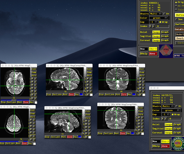
In terms of what I am seeing, I have attached a pic of the original eddy and mrconvert file on locked screens, suggesting they are not in the same location. I confirmed this by overlapping the two images and also see they are shifted from each other. This pic is reported in voxel indices.

Overlap image: Underlay is original eddy file and overlap is test.nii after conversion.

  1. On a separate note in testing it looks like the bvecs format I need for 3dAllineate and CAMINO’s tensor module are similar to what was originally specified in mrconvert prior to changing the FSL bvecs output to account for the legacy analyze format. Is there a version of mrconvert available with the original interpretation of the bvecs file?

Thanks,
Ajay