# Streamlines tractography output problem
**URL:** https://community.mrtrix.org/t/streamlines-tractography-output-problem/903
**Category:** Uncategorized
**Created:** [May 17, 2017, 9:51pm UTC](https://community.mrtrix.org/t/streamlines-tractography-output-problem/903 "2017-05-17T21:51:34Z")
**Posts on this page:** 20
**Page:** 1
### Author:  [@SuperClear](https://community.mrtrix.org/u/SuperClear)
#### Post date: [May 17, 2017, 9:51pm UTC](https://community.mrtrix.org/t/streamlines-tractography-output-problem/903/1 "2017-05-17T21:51:34Z")
Hi, all,
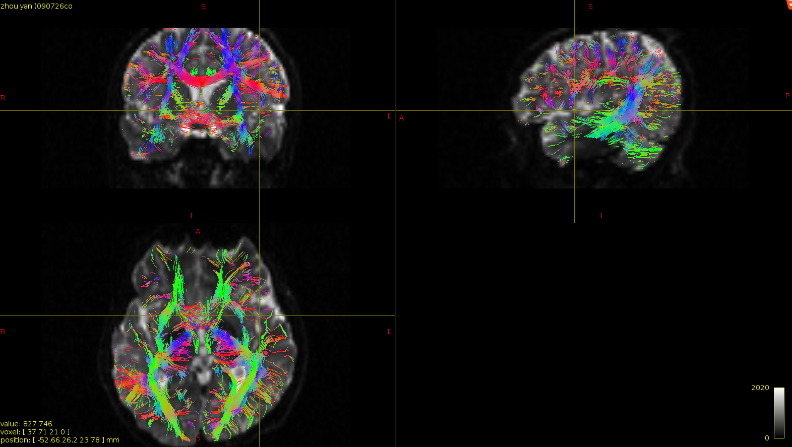
Have you ever meet this problem? I did streamlines tractography and the output seems abnormal.
Here is the code:
```
tckgen -algorithm SD_Stream -cutoff 0.25 -angle 77 DTI_fod.mif DTI_StreamTracking_FA0.25_ang77.tck -seed_grid_per_voxel DTI_mask.nii 1 -mask DTI_mask.nii
```
and the outputs as are shown:
Ortho View:
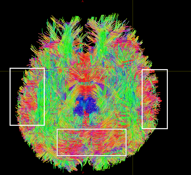
Volume Rendering:
The fibers of the other papers:
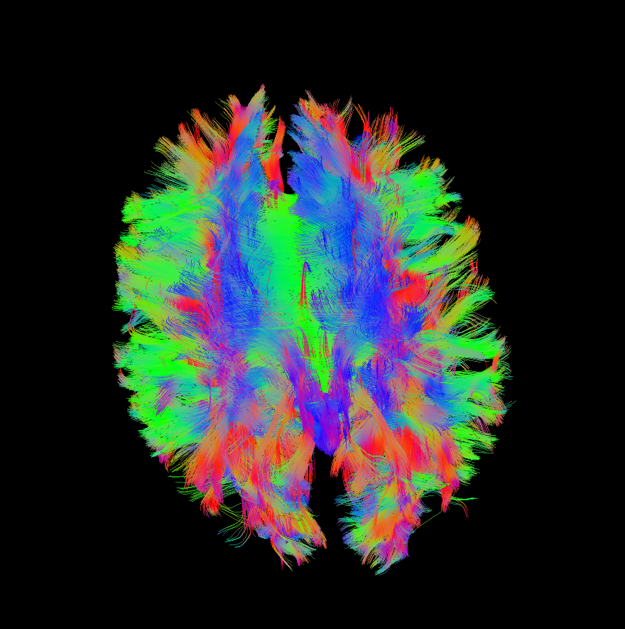
In volume rendering view: In the left and right white rectangles, the fibers have many short fibers perpendicular to the others. What I consider most is the white rectangle in the bottom, compared with the third picture, there are sets of red transversal fibers. It seems there are some fibers just lay down on the surface of the brain cortex.
Maybe there’s some problem when I do streamline tractography. I have no idea now, does anyone have some ideas?
Thanks,
Chaoqing
---
### Author:  [@jdtournier](https://community.mrtrix.org/u/jdtournier)
#### Post date: [May 18, 2017, 7:37am UTC](https://community.mrtrix.org/t/streamlines-tractography-output-problem/903/2 "2017-05-18T07:37:48Z")
There’s nothing that unusual about your results. I personally don’t recommend using deterministic tractography (which the `sd_stream` algorithm is), for a whole number of reasons, which I won’t go into here. But at least you’re using sensible parameters with it (reminds me that we still need to fix up the default angle parameter - I’ll do that ASAP).
The spurious streamlines that you see through cortical regions are also not unexpected particularly when using lower _b_-values (I assume this is using _b_ = 1000 s/mm² data?). This is the kind of issue that [ACT](http://mrtrix.readthedocs.io/en/latest/quantitative_structural_connectivity/act.html) was designed to deal with, I strongly recommend you consider adding that approach to your workflow. There are other approaches to minimise the occurrence of these issues (higher _b_-values, using a white matter mask, …), but none of them are as good as using ACT itself.
One slight concern is that the spurious fibres seem to run predominantly in the AP direction, which could indicate a systematic bias, maybe due to eddy currents or some other subtle instability. Best thing to do to verify this would be to run your acquisition protocol on a phantom and check that the anisotropy is near zero and the primary eigenvector direction is genuinely random (you’ll need to use a slow diffusing phantom for this, e.g. agar, not water, otherwise you’ll get no signal in the DWIs…).
---
### Author:  [@ThijsDhollander](https://community.mrtrix.org/u/ThijsDhollander)
#### Post date: [May 18, 2017, 9:44am UTC](https://community.mrtrix.org/t/streamlines-tractography-output-problem/903/3 "2017-05-18T09:44:20Z")
> [@SuperClear](#):
>
> It seems there are some fibers just lay down on the surface of the brain cortex.
> [@jdtournier](#):
>
> One slight concern is that the spurious fibres seem to run predominantly in the AP direction
Those in the AP direction are mostly those at the left/right sides, right? Not per se AP direction over the whole brain? That’s consistent with the “laying down on the surface of the brain” bit… which could potentially also suggest a problem with motion between volumes? Have you done proper motion correction across the series of images?
---
### Author:  [@SuperClear](https://community.mrtrix.org/u/SuperClear)
#### Post date: [May 19, 2017, 8:28am UTC](https://community.mrtrix.org/t/streamlines-tractography-output-problem/903/4 "2017-05-19T08:28:26Z")
Yeah, right, the b-value is 1000s/mm². And the data comes from the hospital, I really don’t know how to verify this…
I’m going to see how to use ACT. I almost don’t know anything about ACT.
Thanks for your suggestion~~ grinning:
---
### Author:  [@SuperClear](https://community.mrtrix.org/u/SuperClear)
#### Post date: [May 19, 2017, 8:38am UTC](https://community.mrtrix.org/t/streamlines-tractography-output-problem/903/5 "2017-05-19T08:38:17Z")
Yeah, the transversal fibres are just on the left side or on the right side. They are not per se AP direction over the whole brain. In fact, I didn’t do any motion correction across the images, probably, the reflect the problem with motion. I didn’t take it into account … 😲
---
### Author:  [@rsmith](https://community.mrtrix.org/u/rsmith)
#### Post date: [May 19, 2017, 10:42am UTC](https://community.mrtrix.org/t/streamlines-tractography-output-problem/903/6 "2017-05-19T10:42:56Z")
Throwing a few more thoughts into the hat:
- Other softwares / articles commonly use a more conservative tracking threshold, e.g. FA \> 0.2; _MRtrix3_ defaults to FOD amplitude \> 0.1. This will result in generation of streamlines in areas where other algorithms would forbid them, but also reduces the prevalence of false terminations.
- Other softwares / articles also commonly use a longer minimum length criterion, e.g. 20-30mm; _MRtrix3_ defaults to 5 voxels (~ 10mm). This permits reconstruction of short connections that do exist in the brain, but can appear “noisy”, whereas other algorithms put an emphasis on reconstruction of the major white matter bundles only.
- CSD is more sensitive to both crossing fibre populations with small volume, and more complex fibre configurations, than many other models. But as previously, this can also appear as “noisy” streamlines reconstruction.
The second image you provided uses red for AP direction and green for LR direction; it’s very off-putting 😕
> The spurious streamlines that you see through cortical regions are also not unexpected particularly when using lower b-values (I assume this is using b = 1000 s/mm² data?). This is the kind of issue that ACT was designed to deal with, I strongly recommend you consider adding that approach to your workflow. There are other approaches to minimise the occurrence of these issues (higher b-values, using a white matter mask, …), but none of them are as good as using ACT itself.
Throwing multi-tissue CSD into the mix here as well. By assigning the signal emanating from grey matter to grey matter, and only using the anisotropic white matter signal contribution for tracking, streamlines at / near the cortex are more reliable and “clean-looking”, since in single-tissue CSD the approximately isotropic grey matter signal results in non-isotropic noise-sensitive FODs.
---
### Author:  [@SuperClear](https://community.mrtrix.org/u/SuperClear)
#### Post date: [May 20, 2017, 8:31pm UTC](https://community.mrtrix.org/t/streamlines-tractography-output-problem/903/7 "2017-05-20T20:31:00Z")
Cool!
Thanks for your deep analysis. I benefit a lot from your explanation. 😀
---
### Author:  [@SuperClear](https://community.mrtrix.org/u/SuperClear)
#### Post date: [November 8, 2017, 9:04pm UTC](https://community.mrtrix.org/t/streamlines-tractography-output-problem/903/8 "2017-11-08T21:04:30Z")
Hi, Donald,
I mainly test ACT method on two data sets, and what I concerned most are the following two points:
1. The corpus callosum fibers are incomplete, as shown in Fig.1-5 and Fig 2-5.
2. The tckgen results a lot of short fibers, as shown in Fig 1-4.
I also had tried:
A) increase fiber number: up to 1M;
B) Change mask: white matter mask → whole brain mask.
C) seeding mechanisms: `-seed_dynamic` and `-seed_gmwmi`
But the comeout has no any improvement.
Can you provide me some suggestion?
Thanks,
Chaoqing
* * *
**1. ACT with data1**
I register DTI and T1 to MNI152 space as [Lucius](http://community.mrtrix.org/t/registration-of-structural-and-diffusion-weighted-data/203/22) suggested.
Fig. 1-0. ( mrview: T1, DTI, WM, GMWMI in MNI152 space)
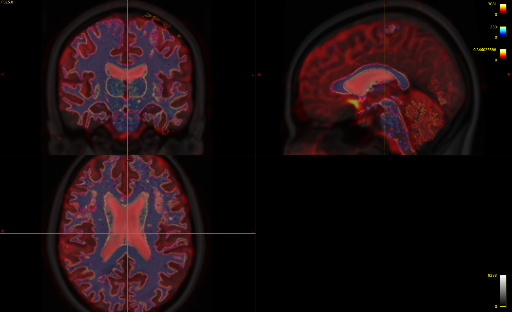
Fig. 1-1. ( response function )
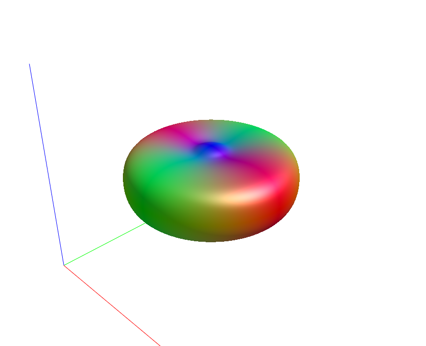
Fig. 1-2. (white matter mask)

Fig. 1-3. (Fiber orientation distribution)
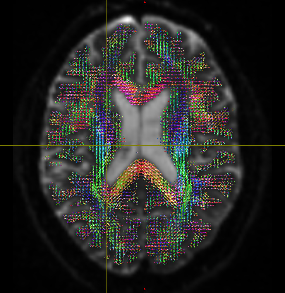
Fig. 1-4. (tckgen -act result)
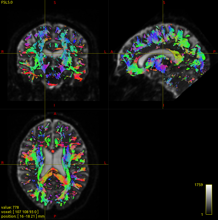
Fig. 1-5. (The rendering result)
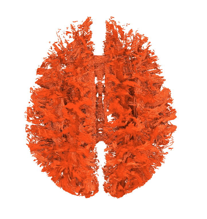
[ACT commands]:
> 1. 5ttgen fsl t1\_2013\_freesufer\_in\_MNI152.nii.gz t1\_2013\_freesufer\_in\_MNI152\_nocrop\_5TT.nii.gz -nocrop
>
> 2. 5tt2gmwmi t1\_2013\_freesufer\_in\_MNI152\_nocrop\_5TT.nii.gz t1\_2013\_freesufe
> r\_in\_MNI152\_nocrop\_5TT\_gmwmi.mif
>
> 3. dwi2response tournier DTI\_2013\_freesurfer\_in\_MNI152.nii.gz DTI\_2013\_free
> surfer\_in\_MNI152\_fswm\_response.txt -mask t1\_2013\_freesufer\_wm\_in\_MNI152.nii.gz -fslgrad DTI\_2013.bvecs DTI\_2013.bvals
>
> 4. dwi2fod csd DTI\_2013\_freesurfer\_in\_MNI152.nii.gz DTI\_2013\_freesurfer\_in\_
> MNI152\_fswm\_response.txt DTI\_2013\_freesurfer\_in\_MNI152\_fswm\_fod.mif -mask t1\_2013\_freesufer\_wm\_in\_MNI152.nii.gz -fslgrad DTI\_2013.bvecs DTI\_2013.bvals
>
> 5. tckgen -act t1\_2013\_freesufer\_in\_MNI152\_nocrop\_5TT.nii.gz DTI\_2013\_free
> surfer\_in\_MNI152\_fswm\_fod.mif DTI\_2013\_freesurfer\_in\_MNI152\_fswm\_act\_gmwmi\_backtrack\_0.1M.tck -crop\_at\_gmwmi -seed\_gmwmi t1\_2013\_freesufer\_wm\_in\_MNI152.nii.gz -backtrack -select 100000
* * *
**2. ACT with data2(An example data)**
Fig. 2-0 ( mrview: T1, DTI, WM, GMWMI )
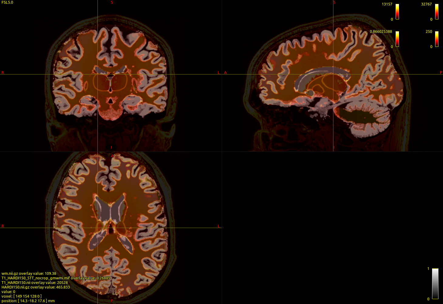
Fig. 2-1. ( response function )
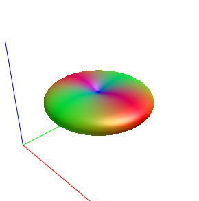
Fig. 2-3. (Fiber orientation distribution)
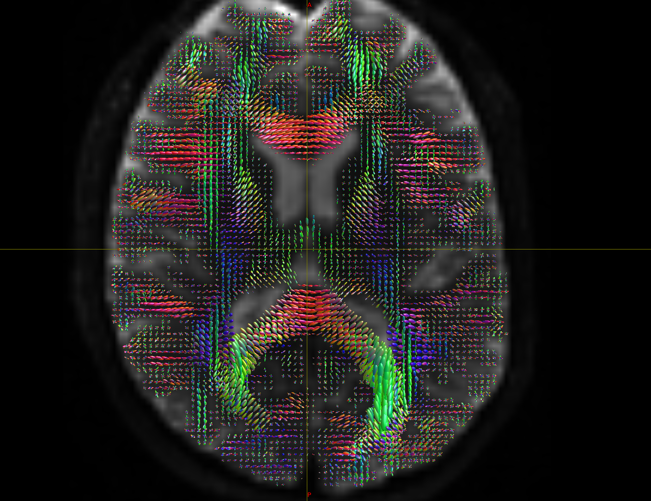
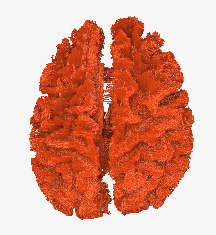
Fig. 2-4. (tckgen -act result)

Fig. 2-5. (The rendering result)
[ACT commands]:
> 1. 5ttgen fsl T1\_HARDI150.nii.gz T1\_HARDI150\_5TT\_nocrop.mif -nocrop
>
> 2. dwi2response tournier -fslgrad HARDI150.bvec HARDI150.bval HARDI150.nii.gz HARDI150\_response.txt
>
> 3. dwi2fod csd HARDI150.nii.gz HARDI150\_response.txt HARDI150\_WMvolume\_fod.mif -mask T1\_HARDI150\_5TT\_nocrop\_WMvolume\_3D\_HARDItemplate.nii.gz -fslgrad HARDI150.bvec HARDI150.bval
>
> 4. 5tt2gmwmi T1\_HARDI150\_5TT\_nocrop.mif T1\_HARDI150\_5TT\_nocrop\_gmwmi.mif
>
> 5. tckgen -act T1\_HARDI150\_5TT\_nocrop.mif HARDI150\_WMvolume\_fod.mif HARDI150\_Wmvolume\_act\_0.1M\_backtrck.tck -crop\_at\_gmwmi -seed\_gmwmi T1\_HARDI150\_5TT\_nocrop\_gmwmi.mif -backtrack -select 100000
* * *
---
### Author:  [@jdtournier](https://community.mrtrix.org/u/jdtournier)
#### Post date: [November 8, 2017, 10:04pm UTC](https://community.mrtrix.org/t/streamlines-tractography-output-problem/903/9 "2017-11-08T22:04:54Z")
OK, for Data1, it’s hard to tell, but there’s a few things to look at:
- what do the WM ODFs (`HARDI150_WMvolume_fod.mif`) look like in the corpus callosum in those problematic regions?
- what does the 5TT image (`T1_HARDI150_5TT_nocrop.mif`) look like in the same region?
- are you sure your WM ODFs are correctly oriented? It’s hard to tell from your screenshot, but given what you show in Data2, there’s a good chance that’s where the problem is (see below).
For Data2, your figure 2-3 very clearly shows that either the X or Y component has been inverted - your FODs don’t point in the expected anatomical directions. This means there’s a problem with your gradient table import. Where did your `DTI_2013.bvecs` come from? I think that’s the issue…
Assuming you’re confident that your bvecs are correct, one possible explanation would be [this previous bug](http://www.mrtrix.org/2016/04/15/bug-in-fsl-bvecs-handling/), long since fixed. If that’s the case, you might be able to deal with this by inverting the strides for the X component of your `DTI_2013_freesurfer_in_MNI152.nii.gz` image, but that very much depends what the strides are currently. Assuming
```auto
mrinfo DTI_2013_freesurfer_in_MNI152.nii.gz -stride
```
outputs `1 2 3 4`, then try
```auto
mrconvert DTI_2013_freesurfer_in_MNI152.nii.gz -stride -1,2,3,4 DTI_2013_freesurfer_in_MNI152_new.nii.gz
```
and use that file for the subsequent processing, there’s a chance that might fix it… Note that this relies on an up to date version of MRtrix3 (i.e. one that correctly handles the FSL bvecs).
---
### Author:  [@SuperClear](https://community.mrtrix.org/u/SuperClear)
#### Post date: [November 8, 2017, 10:31pm UTC](https://community.mrtrix.org/t/streamlines-tractography-output-problem/903/10 "2017-11-08T22:31:43Z")
Hi, Rob,
I have some puzzles on `SD_STREAM` determination tractography:
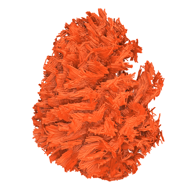
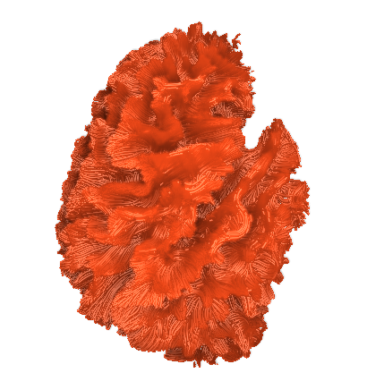
The tckgen results are hard fibers(Fig. 3-1 and Fig.3-2), especially comared with Fig. 4-1 and Fig. 4-2.
Do you know what may cause the problem? Do we need to do fiber smooth operation?
Also,I tried:
A) change masks: the whole brain mask, WM mask created by FreeSurfer.
B) change seeding mechanisms: `-seed_dynamic` and `-seed_image mask`
C) change angles: 30 - 45.
However, the outputs have the same problem.
Thanks,
Chaoqing
* * *
The data that I use is the example data ( as shown previously in the current topic: [“ACT with data2”](http://community.mrtrix.org/t/streamlines-tractography-output-problem/903/8)
Here are the rendering of the determination tractography output:
Fig. 3-1( axial view )

Fig. 3-2( sagittal view )
[SD\_Stream commands]:
> 1. 5ttgen fsl T1\_HARDI150.nii.gz T1\_HARDI150\_5TT\_nocrop.mif -nocrop
>
> 2. mrconvert -coord 3 2 T1\_HARDI150\_5TT\_nocrop.mif T1\_HARDI150\_5TT\_nocrop WMvolume.nii.gz
>
> 3. mrmath T1\_HARDI150\_5TT\_nocrop\_WMvolume.nii.gz mean -axis 3 T1\_HARDI150\_5TT\_nocrop\_Wmvolume\_3D.nii.gz
>
> 4. mrtransform T1\_HARDI150\_5TT\_nocrop\_WMvolume\_3D.nii.gz -template HARDI150.nii.gz T1\_HARDI150\_5TT\_nocrop\_Wmvolume\_3D\_HARDItemplate.nii.gz
>
> 5. dwi2response tournier -fslgrad HARDI150.bvec HARDI150.bval HARDI150.nii.gz HARDI150\_response.txt (shview HARDI150\_response.txt)
>
> 6. dwi2fod csd HARDI150.nii.gz HARDI150\_response.txt HARDI150\_WMvolume\_fod.mif -mask T1\_HARDI150\_5TT\_nocrop\_WMvolume\_3D\_HARDItemplate.nii.gz -fslgrad HARDI150.bvec HARDI150.bval
>
> 7. tckgen -algorithm SD\_Stream HARDI150\_WMvolume\_fod.mif HARDI150\_WMvolume\_StreamTracking\_pervoxel.tck -seed\_grid\_per\_voxel T1\_HARDI150\_5TT\_nocrop\_WMvolume\_3D\_HARDItemplate.nii.gz 2 -mask T1\_HARDI150\_5TT\_nocrop\_Wmvolume\_3D\_HARDItemplate.nii.gz -minlength 10
* * *
Fiber tracking result from Zhejiang University of Technology with the same data.
I don’t know the specific algorithm of them, just get the data from them, and the rendering results looks cool.
Fig. 4-1 (axial view )
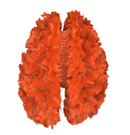
Fig. 4-2 ( sagittal view )
---
### Author:  [@Lucius](https://community.mrtrix.org/u/Lucius)
#### Post date: [November 9, 2017, 11:03am UTC](https://community.mrtrix.org/t/streamlines-tractography-output-problem/903/11 "2017-11-09T11:03:56Z")
> [@jdtournier](#):
>
> I personally don’t recommend using deterministic tractography (which the sd\_stream algorithm is), for a whole number of reasons, which I won’t go into here.
Dear @jdtournier, we’re quite interested in that specific topic. In the clinical setting, the neuronavigation applications use determistic tractography algorithms (I think Brainlab uses a mixture between FACT and TEND). I prefer to have at least a comparison of probabilistic and deterministic based results to get a better overview over the patients wm structure. To overcome that problem, I sometimes burn the probabilistic tracts on a dicom set and then feed it to the planning software (unfortunately not a straight forward process) or just use the images then.
Since at our clinic most of the colleagues are familiar with a deterministic algorithm but usually not with the probabilistic ones, it’s not always easy to implement it.
So, to work on the general acceptance and familiarity, it would be wonderful if you could provide a few good arguments for prob. tractography and some reasons why not to (only) use det tractography.
Or if anyone knows about good papers concerning that topic, I’d be very thankful as well.
Best regards and thanks for your much appreciated mrtrix!
Lucius
---
### Author:  [@jdtournier](https://community.mrtrix.org/u/jdtournier)
#### Post date: [November 9, 2017, 1:58pm UTC](https://community.mrtrix.org/t/streamlines-tractography-output-problem/903/12 "2017-11-09T13:58:14Z")
> [@SuperClear](#):
>
> The tckgen results are hard fibers(Fig. 3-1 and Fig.3-2), especially comared with Fig. 4-1 and Fig. 4-2.
I’m not sure what you mean by ‘hard fibers’ here, but I expect you mean they look a bit ‘blocky’ - for want of a better word? That’s actually part of the reason why I don’t recommend the use of the deterministic streamlines algorithm on SH fods - see [this paper](http://onlinelibrary.wiley.com/doi/10.1002/ima.22005/abstract), particularly Figure 2, for an description of (one of) the problems. Assuming the other images were also generated using _MRtrix3_ (don’t know whether this is in fact the case?), then the default algorithm, iFOD2, would give you results similar to this (with decent input data) - it’s probabilistic, which I do recommend for the reasons outlined in the [same MRtrix paper](http://onlinelibrary.wiley.com/doi/10.1002/ima.22005/abstract) as above.
---
### Author:  [@jdtournier](https://community.mrtrix.org/u/jdtournier)
#### Post date: [November 9, 2017, 2:47pm UTC](https://community.mrtrix.org/t/streamlines-tractography-output-problem/903/13 "2017-11-09T14:47:26Z")
> [@Lucius](#):
>
> So, to work on the general acceptance and familiarity, it would be wonderful if you could provide a few good arguments for prob. tractography and some reasons why not to (only) use det tractography.
I appreciate your situation… This is an argument that I’ve had many times in the past, and it’s still far from resolved. My point of view has always been that there are many sources of uncertainty in diffusion MRI: noise of course, but more importantly also the inevitable fibre dispersion (due to fanning, curvature, crossings, but also jitter in the individual axon trajectories), and the inherent blurring effect of the diffusion measurement (its angular resolution is limited by the inherent smoothness of the diffusion profile / response function). Deterministic streamlines ignores all sources of uncertainty and reports the single ‘best guess’. This runs an enormous risk of missing existing connections – i.e. high false negatives.
For an application as critical as neurosurgery planning, I would argue that such false negatives are very dangerous: this would give the surgeon a false sense of security, implying for example that no eloquent white matter pathways run though the planned resection, leading to otherwise avoidable loss of function (e.g. [this paper](http://www.sciencedirect.com/science/article/pii/S1053811904007761)). So from this point of view, I would _always_ advocate probabilistic tractography since it is designed to produce the full _distribution_ of likely pathways.
Note that this undeniably involves many more false positives (see [this paper](http://www.pnas.org/content/111/46/16574) on the topic). This is often stated as a drawback, making the results messier and harder to interpret. However, I would argue that it is better to provide surgeons with the fullest possible picture of the likely tracks in the region, from which they can then make informed decisions about what is plausible and what isn’t. The alternative (deterministic tracrography) is to present results known to be potentially incomplete – a strategy I’d personally consider to be reckless and indefensible.
As to relevant publications on the topic, you’re in luck: [this just came out](https://www.nature.com/articles/s41467-017-01285-x)… See figure 3 in particular. Also relevant, [this paper](https://www.ncbi.nlm.nih.gov/pubmed/23540269) comparing DTI and CSD based tractography might be of interest – it does make a subtly different point from what you’re asking, but the issue of probabilistic vs. deterministic is also discussed. I’ve no doubt there may be other relevant papers out there, these are just a couple to get you started. Hopefully other users will point out a few more…
---
### Author:  [@Lucius](https://community.mrtrix.org/u/Lucius)
#### Post date: [November 9, 2017, 6:31pm UTC](https://community.mrtrix.org/t/streamlines-tractography-output-problem/903/14 "2017-11-09T18:31:42Z")
Thank you very much for this great explanations, arguments and links. The users and developers of planning software should really know more and about those issues and consider solutions.
---
### Author:  [@SuperClear](https://community.mrtrix.org/u/SuperClear)
#### Post date: [November 10, 2017, 10:33am UTC](https://community.mrtrix.org/t/streamlines-tractography-output-problem/903/15 "2017-11-10T10:33:22Z")
Hi, Donald,
**1. ACT with data2(An example data)**
The FODs ( `HARDI150_WMvolume_fod.mif` ) is not in expected anatomical directions(as shown in Fig. 5.1).
The 5TT image (`T1_HARDI150_5TT_nocrop.mif`) is shown in Fig.5.2.
However, I cannot fix it by using `mrconvert -stride` command, I tried:
`mrconvert HARDI150.nii.gz -stride -1,2,3,4 HARDI150_StrideX.nii.gz` ( Fig.5.3 )
` mrconvert HARDI150.nii.gz -stride 1,-2,3,4 HARDI150_StrideY.nii.gz` ( Fig.5.4 )
` mrconvert HARDI150.nii.gz -stride -1,-2,3,4 HARDI150_StrideXY.nii.gz` ( Fig.5.5 )
I finally fix HARDI150 FODs by inverse the second column of ` HARDI150.bvecs` as shown in Fig 5.6 ( `HARDI150.bvecs` maybe not generated by Mrtrix3 ). Fig 5.7 shown the corpus callosum region. However, it is not able to generate the fibers in corpus callosum region( see Fig 5.9 and Fig 5.10 ).
Do you have any ideas? I still cannot find the solution.
* * *
**2. ACT with data1**
The `DTI_2013.bvecs` is created by Mrtrix3 command:
`mrconvert 2013-02-06_10_56_37.0/ -export_grad_fsl DTI_2013.bvecs DTI_2013_bvals DTI_2013.nii.gz`
① In native anatomical space:
`DTI_2013.nii.gz` is 4D image and t1\_2013.nii.gz is the corresponding 3D image. I use the original data: ( `DTI_2013.nii.gz / t1_2013.nii.gz` ) to generate the fod image ( `DTI_2013_fod.mif` ) , the fod image correctly shows the anatomical direction, see Fig 6.1.
Then I do `recon-all` command of FreeSurfer to generate cortical parcellations of `t1_2013.nii.gz`. In this way, the `t1_2013.nii.gz` data will naturally go to FreeSurface space ( `t1_2013_freesurfer.nii.gz` ) . So I register `DTI_2013.nii.gz` to `DTI_2013_freesurfer.nii.gz`, [following Lucius’s instruction](http://community.mrtrix.org/t/registration-of-structural-and-diffusion-weighted-data/203/22), They seems registered nicely, see Fig 6.2:
> A. Register DTI\_b0 to T1\_freesurfer:
>
> flirt -in DTI\_2013\_b0.nii.gz -ref t1\_2013\_freesufer\_skulled.nii.gz -omat DTI\_2013\_b0\_to\_t1\_2013\_freesurf\_skulled.mat
>
> flirt -in DTI\_2013\_b0.nii.gz -ref t1\_2013\_freesufer\_skulled.nii.gz -applyxfm -init DTI\_2013\_b0\_to\_t1\_2013\_freesurf\_skulled.mat -out DTI\_2013\_b0\_freesurfer.nii.gz
>
> B. Register DTI to T1\_freesurfer:
>
> flirt -in DTI\_2013.nii.gz -ref t1\_2013\_freesufer\_skulled.nii.gz -applyxfm -init DTI\_2013\_b0\_to\_t1\_2013\_freesurf\_skulled.mat -out DTI\_2013\_freesurfer.nii.gz
② In FreeSurfer space:
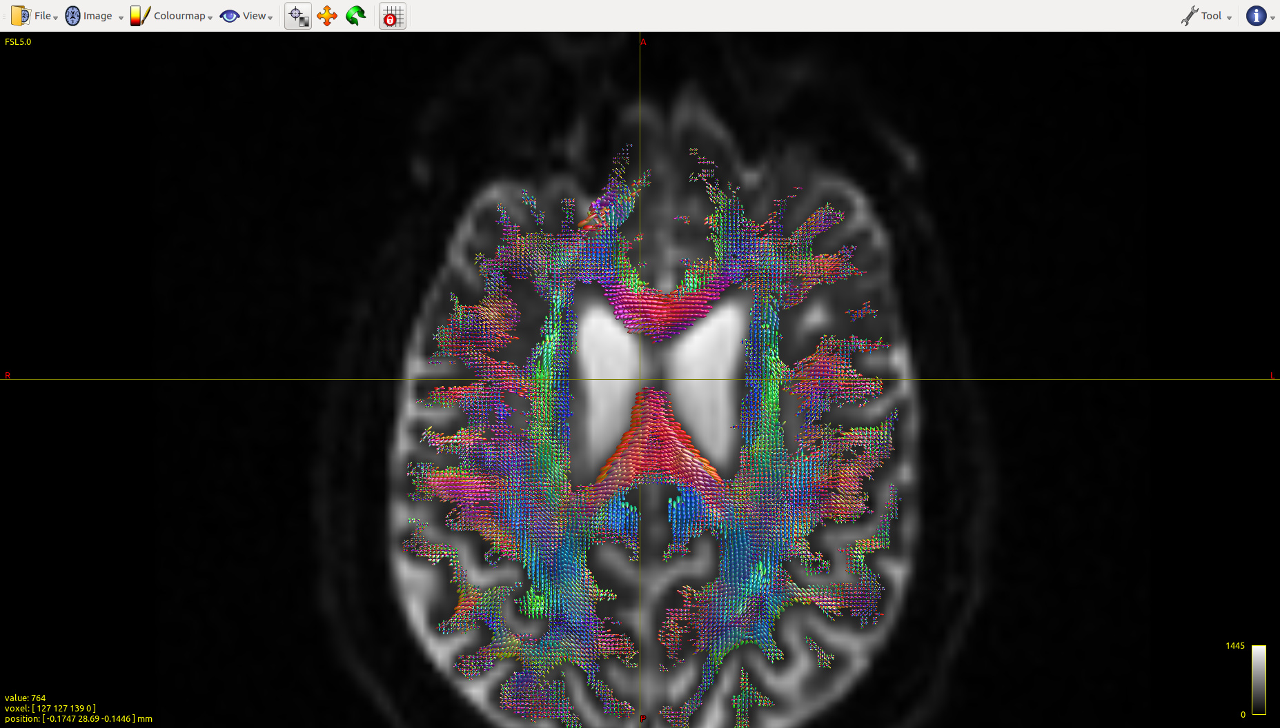
I use the data (` DTI_2013_freesurfer.nii.gz/ t1_2013_freesurfer.nii.gz` ) to generate the fod image (`DTI_2013_freesurfer_fod.mif`), From then on, the fod image can not correctly indicate the anatomical direction, see Fig 6.3. You can find the tensors on the top half the region of corpus callosum are incorrect. (It seems half of the orientation is correct and the other half goes wrong).
③ In MNI152 space:
Then I use the similar registration command to register (`DTI_2013_freesurfer.nii.gz/ t1_2013_freesurfer.nii.gz`) to MNI152 space. The fod image ( `DTI_2013_freesurfer_in_MNI152_fswm_fod.mif` ) certainly incorrectly indicates the anatomical direction, as shown in Fig 1.3.
Does it mean I did wrong registration? I tried `mrconvert -stride` and inverse the second collum of bvecs, the output fod images maintain wrong. I hope to know how does it happen and expect to figure it out.
Sweet Thanks,
Chaoqing
* * *
Fig 5.1 ( HARDI150\_WMvolume\_fod.mif )
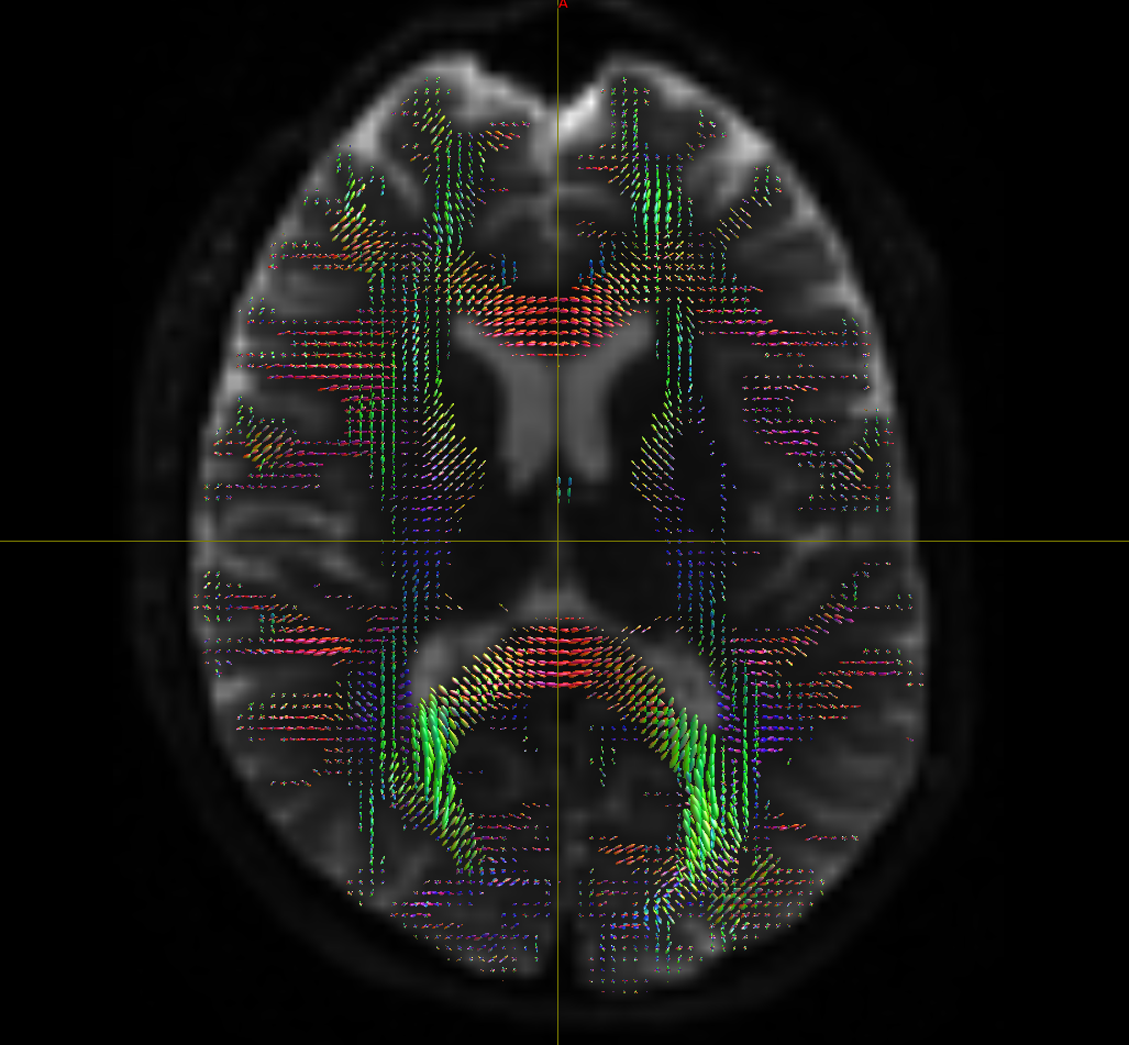
Fig 5.2 ( T1\_HARDI150\_5TT\_nocrop.mif )
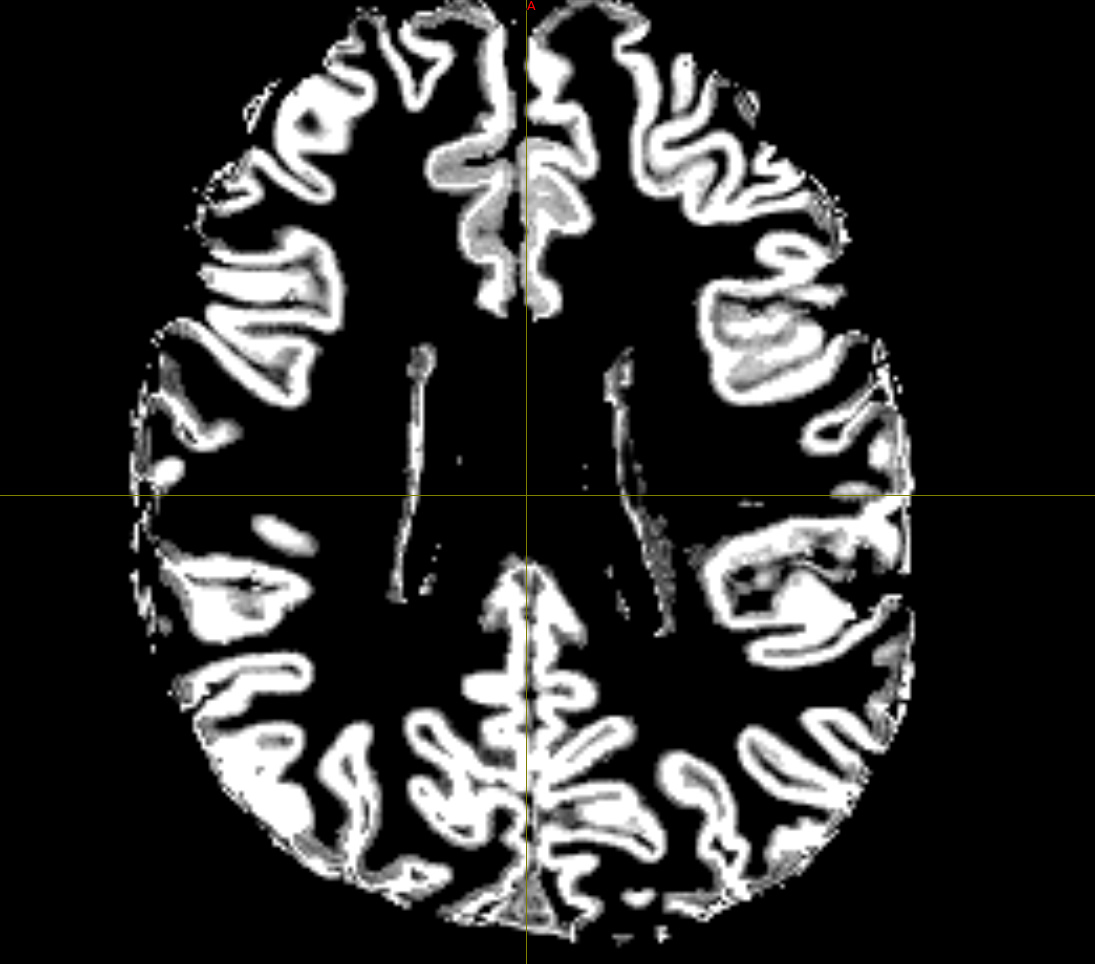
Fig 5.3 ( HARDI150\_StrideX\_WMvolume\_fod.mif )
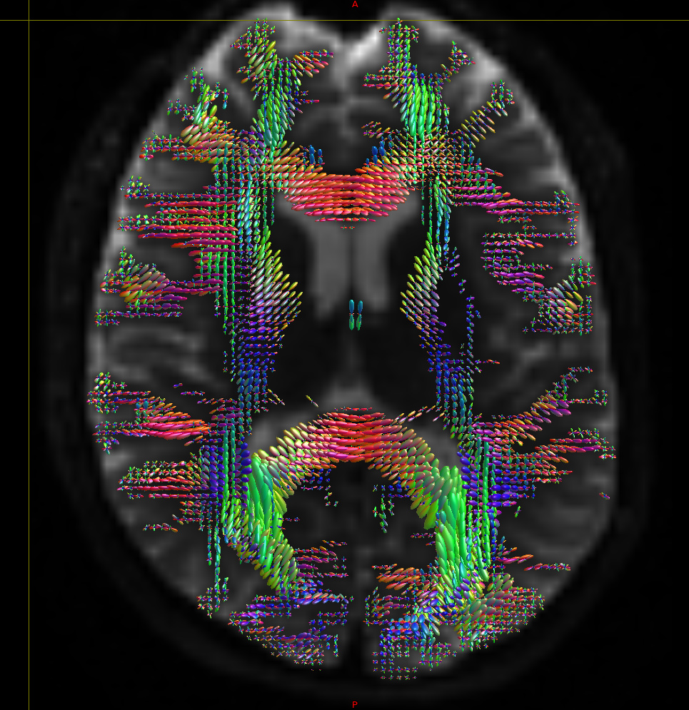
Fig 5.4 ( HARDI150\_StrideY\_WMvolume\_fod.mif )
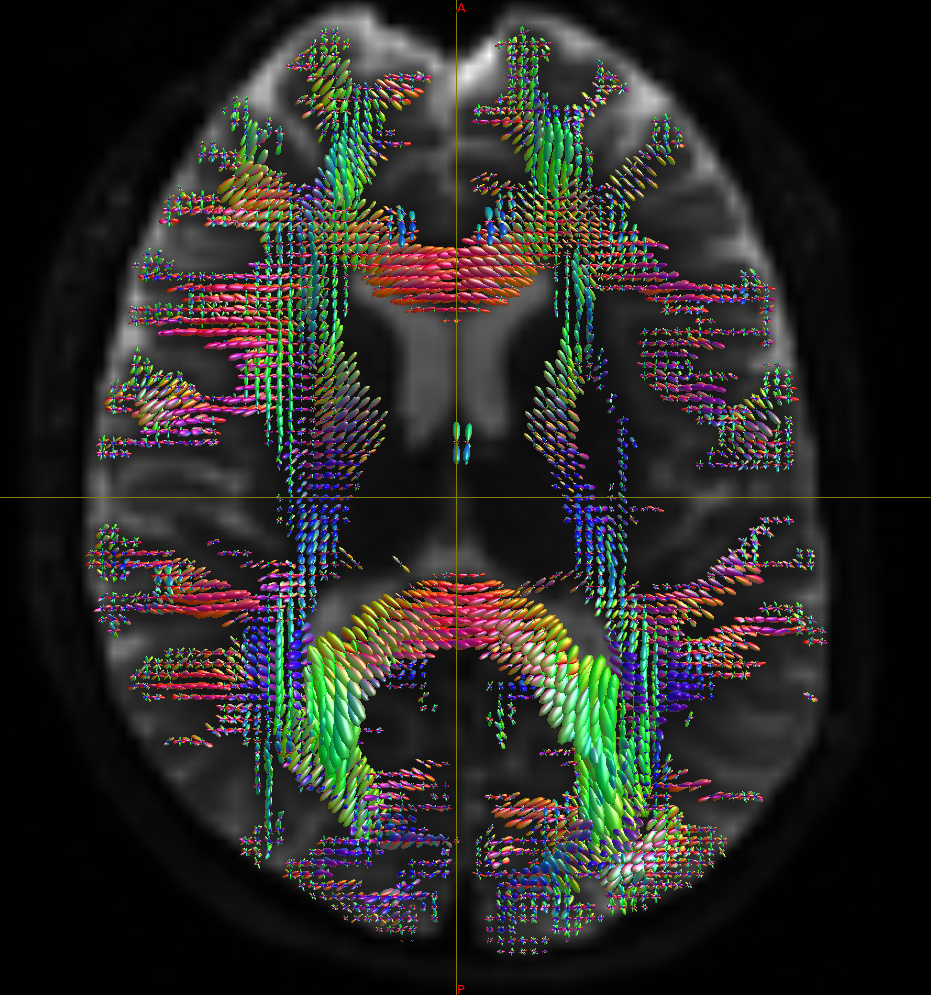
Fig 5.5 (HARDI150\_StrideXY\_WMvolume\_fod.mif )
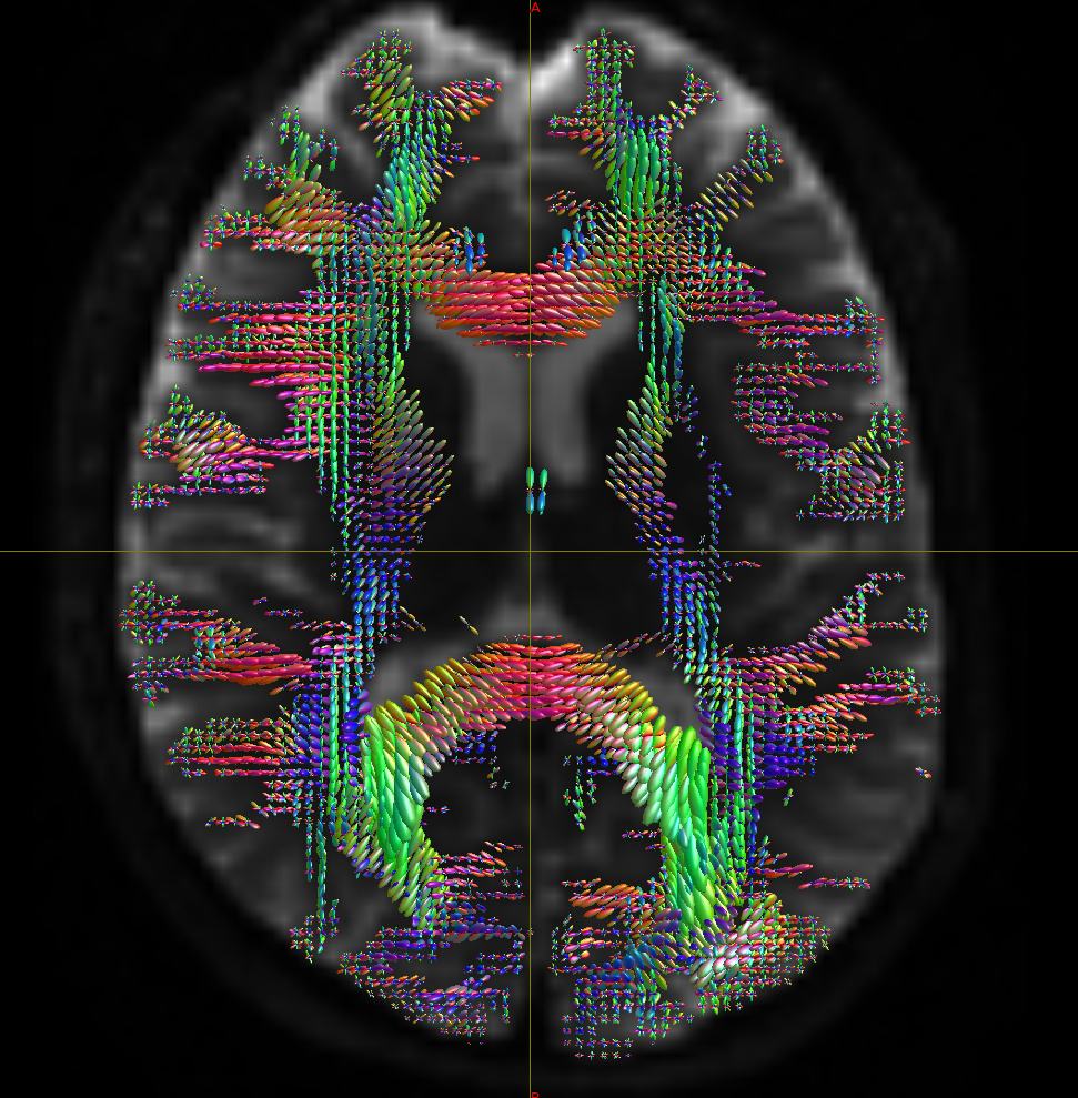
Fig 5.6 (HARDI150\_bvecInverseY\_WMvolume\_fod.mif )
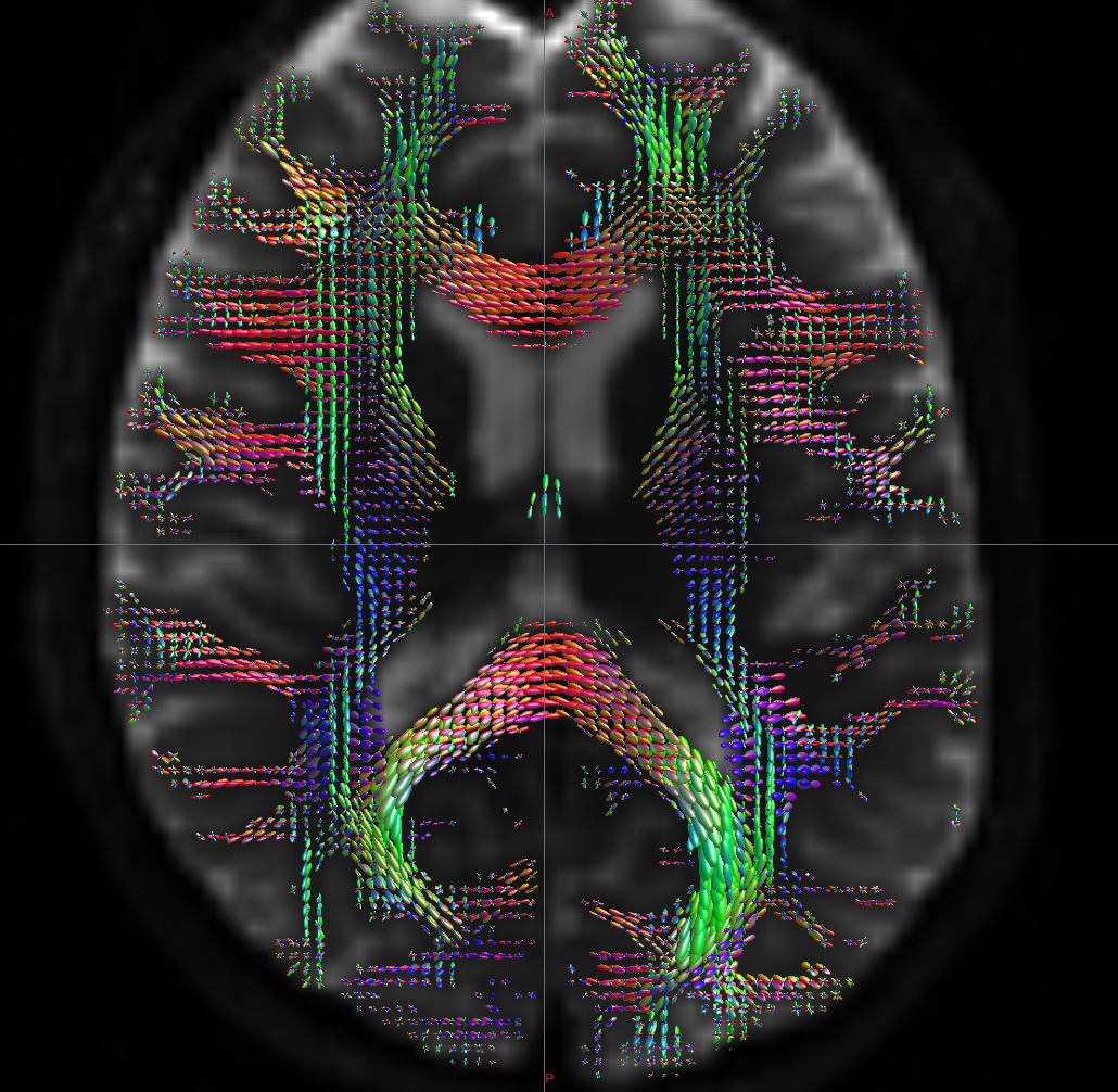
Fig 5.7 (HARDI150\_bvecInverseY\_WMvolume\_fod.mif )
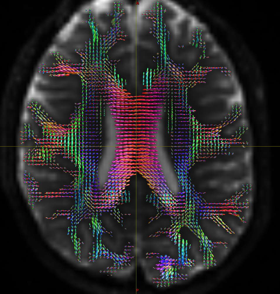
Fig 5.8
( T1\_HARDI150\_5TT\_nocrop.mif and T1\_HARDI150\_5TT\_nocrop\_WMvolume\_3D\_HARDItemplate.nii.gz )
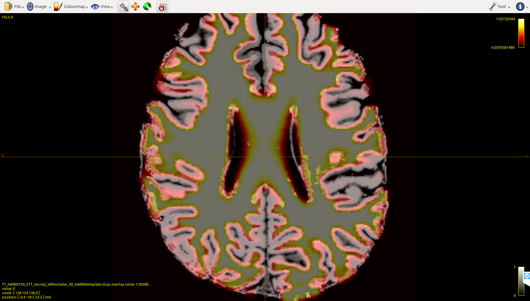
Fig 5.9 ( HARDI150\_bvecInverseY\_WMvolume\_act\_0.1M\_backtrack.tck )
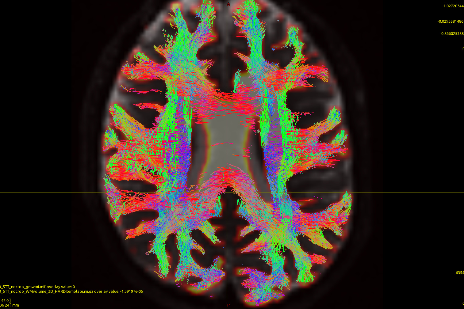
Fig 5.10 ( HARDI150\_bvecInverseY\_WMvolume\_act\_0.1M\_backtrack.tck )
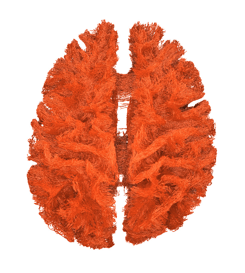
[ACT commands]:
> 1. dwi2response tournier -fslgrad HARDI150\_InverseY.bvecs HARDI150.bvals HARDI150.nii.gz HARDI150\_bvecInverseY\_response.txt
>
> 2. dwi2fod csd HARDI150.nii.gz HARDI150\_bvecInverseY\_response.txt HARDI150\_bvecInverseY\_WMvolume\_fod.mif -mask T1\_HARDI150\_5TT\_nocrop\_WMvolume\_3D\_HARDItemplate.nii.gz -fslgrad HARDI150\_InverseY.bvecs HARDI150.bvals
>
> 3. tckgen -act T1\_HARDI150\_5TT\_nocrop.mif HARDI150\_bvecInverseY\_WMvolume\_fod.mif HARDI150\_bvecInverseY\_WMvolume\_act\_0.1M\_backtrack.tck -crop\_at\_gmwmi -seed\_gmwmi T1\_HARDI150\_5TT\_nocrop\_gmwmi.mif -backtrack -select 100000
* * *
Fig 6.1 ( DTI\_2013\_fod )
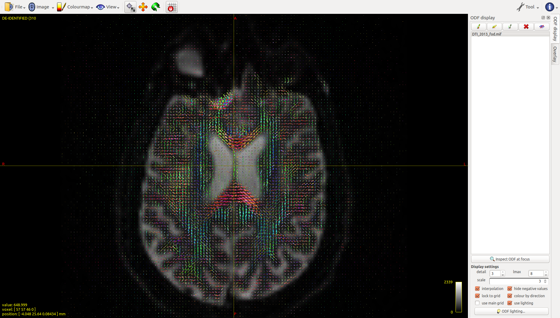
Fig. 6.2 ( mrview : T1, DTI, WM, 5TT image in FreeSurfer space)
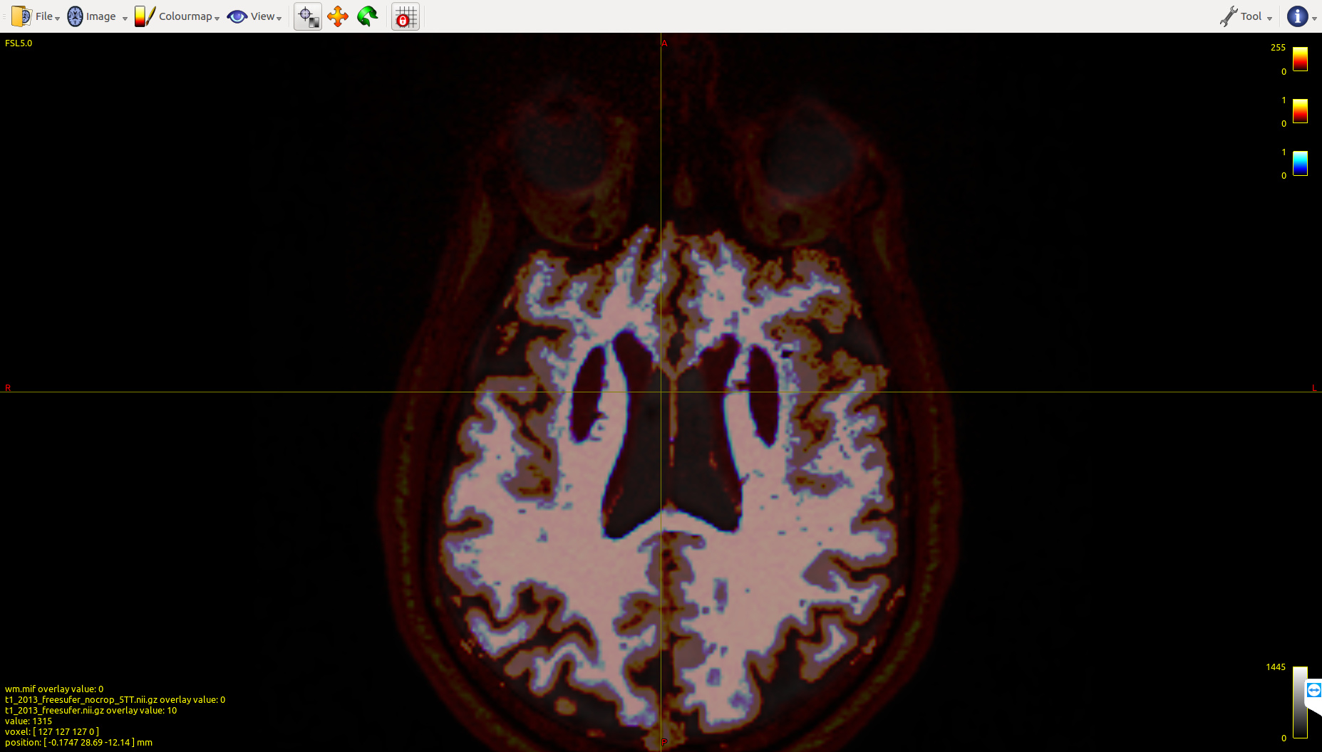
Fig 6.3 ( DTI\_2013\_freesurfer\_fod.mif )
* * *
---
### Author:  [@jdtournier](https://community.mrtrix.org/u/jdtournier)
#### Post date: [November 10, 2017, 4:34pm UTC](https://community.mrtrix.org/t/streamlines-tractography-output-problem/903/16 "2017-11-10T16:34:57Z")
OK, there’s two issues there:
- It seems your Data2 raw data was converted outside of _MRtrix3_? There’s not a lot we can do to fix invalid input data… If this was DICOM format, I’d be willing to look into it, since we take great care to ensure the conversion works as expected for all major manufacturers. But as soon as it’s been converted, it’s pretty much impossible to ensure any subsequent correction actually does the right thing. I strongly recommend starting again from the raw DICOM of you can possibly get access to it.
- for your Data1 case, the main thing is to _never_ transform FOD data (or DWI data in general). These images contain orientation information, and the relationship that information relative to the orientation of the anatomy or scanner will be affected if you reorient the images. Dealing with this requires dedicated handling of the information in the images. Basically, the simplest thing to do to avoid issues is to _never_ transform any DWI or derived data, unless you know the tool you’re using to do this is designed to handle this exact type of data (most won’t). Already register the T1 to the DWI, never the other way round…
---
### Author:  [@rsmith](https://community.mrtrix.org/u/rsmith)
#### Post date: [November 13, 2017, 1:50am UTC](https://community.mrtrix.org/t/streamlines-tractography-output-problem/903/17 "2017-11-13T01:50:37Z")
> However, I cannot fix it by using `mrconvert -stride` command, I tried:
The `-stride` option in `mrconvert` only affects how data from different image axes are arranged into a 1D vector of data for storage in RAM / on a file system. Therefore use of this option will not affect the orientations of different spatial axes relative to one another, or the orientations of any voxel-wise directional information, assuming the images are both written and read by _MRtrix3_. This _can_ have an influence if the images are opened using other softwares, but that depends on how different softwares interpret image heaer transformation information.
---
### Author:  [@SuperClear](https://community.mrtrix.org/u/SuperClear)
#### Post date: [November 13, 2017, 10:47pm UTC](https://community.mrtrix.org/t/streamlines-tractography-output-problem/903/19 "2017-11-13T22:47:45Z")
Hi, Donald,
Thank you very much for your patient explanation!
In my data2 case, I feel very glad to shall the data, but I can’t find the raw DICOM data in my lab, It seems we have lost the raw DICOM data. Or maybe, we didn’t get the original raw data at the beginning. However, if needed, feel free to get the NIFTI data and corresponding T1 data with the dropbox link below.
In my data1 case, I should not transform DWI data to another space, as you said it will damage the original orientation information. So, I try to warp tck file, the corresponding FA image to MNI152 space.
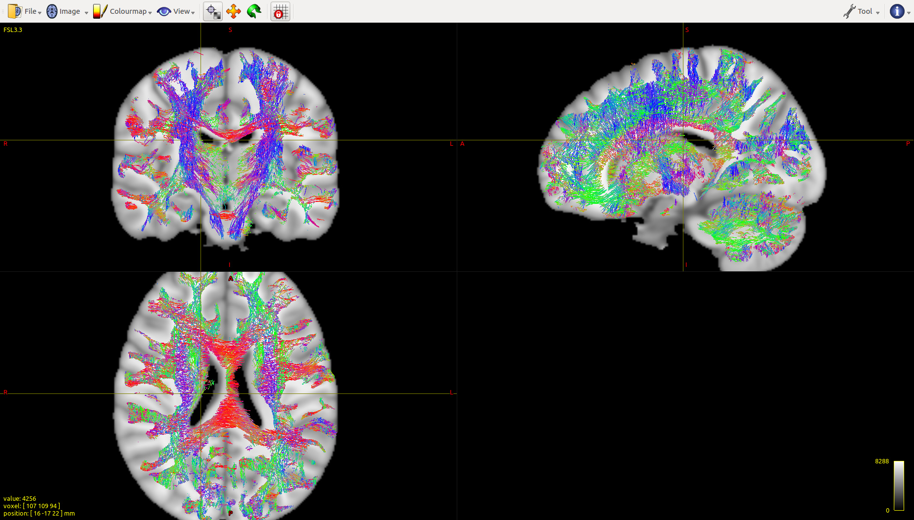
In order to test the warping method, I almost copy [Eloy’s steps](http://community.mrtrix.org/t/warping-tck-files-using-flirt-fsl/459/14). All the steps go without any error. However, there are quite a lot straight lines along with the fibers, especially from the sagittal view ( Fig 7.1 , data1), which is quite different from the warped result with the same steps of data3 (Fig 7.2, data3). Are there any restrictive conditions on warping the images? I guess the problem should hide in my data1.
Also, Comparing with the tck file in subject space, the tck file warped to MNI152 space reserved the same streamline numbers and point numbers. However, the length of each streamline changed. Also, the `fa` value of each point is quite different from the original value in subject space. Is there any method to preserve the original information after warping to MNI152 space?
A lot of Thanks,
Chaoqing
* * *
The dropbox link to HARDI150 data:
> **[HARDI150](https://www.dropbox.com/sh/jzznim2pc487fb3/AAC2qVrHXa7Jdeu-JOwfy2hXa?dl=0)**
>
> Shared with Dropbox
The warping steps of data 1:
> 1. fslchfiletype NIFTI MNI152\_T1\_1mm.nii.gz
>
> 2. ANTS 3 -m CC[MNI152\_T1\_1mm.nii, t1\_2013.nii.gz,1,5] -t SyN[0.5] -r Gauss[2,0] -o T1\_to\_MNI\_synants.nii -i 30x90x20 --use-Histogram-Matching
>
> 3. warpinit MNI152\_T1\_1mm.nii flirtMNI-.nii
>
> 4. for i in {0…2}
> do
> WarpImageMultiTransform 3 flirtMNI-{i}.nii flirtMNI2tck-{i}.nii -R MNI152\_T1\_1mm.nii -i T1\_to\_MNI\_synantsAffine.txt T1\_to\_MNI\_synantsInverseWarp.nii
> done
>
> 5. warpcorrect flirtMNI2tck-.nii flirtMNI2tck\_corr.mif
>
> 6. tcknormalise DTI\_2013\_act\_0.5M.tck flirtMNI2tck\_corr
> .mif DTI\_2013\_act\_0.5M\_WarpMNI152.tck
Fig 7.1 ( data1 warped tckfile ):
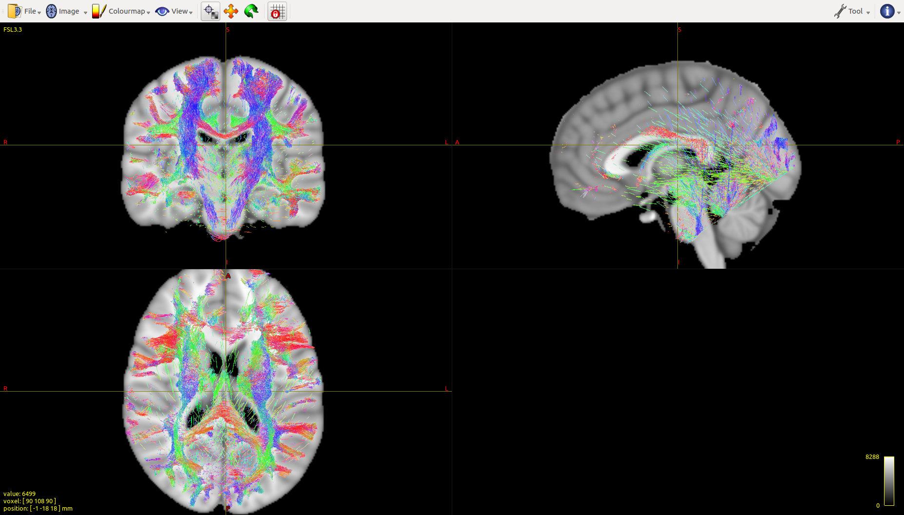
Fig 7.2 (data3 warped tckfile):
The warping steps of data 3 and FA value sampling.
> 1. ANTS 3 -m CC[MNI152\_T1\_1mm.nii, t1\_mpr\_ns\_sag\_iso.nii.gz, 1, 5] -t SyN[0.5] -r Gauss[2,0] -o t1\_disease\_liuyan\_to\_MNI\_synants.nii -i 30x90x20 --use-Histogram-Matching
>
> 2. warpinit MNI152\_T1\_1mm.nii flirtMNI-.nii
>
> 3. for i in {0…2}; do WarpImageMultiTransform 3 flirtMNI-{i}.nii flirtMNI2\_disease\_liuyan\_tck-{i}.nii -R MNI152\_T1\_1mm.nii -i t1\_disease\_liuyan\_to\_MNI\_synantsAffine.txt t1\_disease\_liuyan\_to\_MNI\_synantsInverseWarp.nii ; done
>
> 4. warpcorrect flirtMNI2\_disease\_liuyan\_tck-.nii flirtMNI2\_disease\_liuyan\_tck\_corr.mif
>
> 5. tcknormalise DTI\_30\_average-6\_act\_sift\_0.2M.tck flirtMNI2\_disease\_liuyan\_tck\_corr.mif DTI\_30\_average-6\_act\_sift\_0.2M\_warpMNI152.tck
>
> 6. dwi2tensor –mask DTI\_30\_average-6\_mask.nii DTI\_30\_average-6.nii DTI\_30\_average-6\_tensor.nii –fslgrad DTI\_30\_average-6\_bvecs DTI\_30\_average-6\_bvals
>
> 7. tensor2metric –fa DTI\_30\_average-6\_fa.mif DTI\_30\_average-6\_tensor.nii
>
> 8. tcksample -stat\_tck mean DTI\_30\_average-6\_act\_sift\_0.2M\_warpMNI152.tck DTI\_30\_average-6\_fa.mif DTI\_30\_average-6\_act\_sift\_0.2M\_warpMNI152\_MeanFA.txt
---
### Author:  [@jdtournier](https://community.mrtrix.org/u/jdtournier)
#### Post date: [November 14, 2017, 4:34pm UTC](https://community.mrtrix.org/t/streamlines-tractography-output-problem/903/20 "2017-11-14T16:34:30Z")
OK, a few things I can help with:
- your data does appear to have the bvecs with the x flipped. Quick fix using some Unix shell magic:
- I note your DW encoding is not as optimal as it could be. It seems to have been generated assuming unipolar electrostatic repulsion (?), but even then, I wouldn’t expect to find such a small minimum nearest-neighbour angle:
- the `tcknormalise` issue arise due to the final warp provided to `tcknormalise` covering a smaller extent than the tracks, so that the information for those streamline vertices that map outside the warp is incorrect – all these vertices then map to the same invalid location. The simplest fix in such case will typically be to ensure the warp covers the whole brain, or at least the full tractogram. I’m not sure which bit of your pipeline would need to be modified to deal with this, unless your `MNI152_T1_1mm.nii.gz` is already smaller than the target FoV…?
---
### Author:  [@SuperClear](https://community.mrtrix.org/u/SuperClear)
#### Post date: [November 15, 2017, 8:08am UTC](https://community.mrtrix.org/t/streamlines-tractography-output-problem/903/21 "2017-11-15T08:08:49Z")
Hi, Donald,
Thanks very much for your assistance! I learned a lot from your analysis of HARDI150 data.
For this post is too huge, I switched my problem to another topic: [Image registration for diffusion MRI](https://community.mrtrix.org/t/image-registration-for-diffusion-mri/1316?u=superclear)
Would you help to look into it?
Also, I noticed that the first official MRtrix3 workshop will be held next year. I hope it will be held successfully!
I will struggle for papers. Hope to attend in the future. 😉
Many Thanks and Best wishes!
Chaoqing