Quick recap: directions are flipped along the left-right axis in mrview compared to fslview.
With a recent installation (more recent than April 15 2016, when this fix was released), there should be no mismatch. So there are two possibilities that I can think of:
Then to really verify what date this corresponds to, take the SHA1 checksum, which in the example above is the last bit of the version string, minus the initial ‘g’: 100da720. Then from your MRtrix3 installation:
$ git log 100da720
commit 100da72015f1fa9541b94a1f28d71172029b46f5 (master)
Merge: be66a20a 63664af0
Author: Robert Smith <robert.smith@florey.edu.au>
Date:   Tue Jul 25 10:39:42 2017 +1000

    Merge pull request #1069 from MRtrix3/properties_get_step_size

    Tractography::Properties::get_step_size() function
From which you can read the commit date.
You are using a buggy version of fslview. If I remember correctly, fslview version 4.0 was affected by exactly the same bug that we fixed back in April 2016… Previous versions of fslview were not affected, and I’m assuming more recent versions will work fine too.
In both cases, you can ‘fix’ this by changing the strides in the NIfTI image to LAS (the opposite to the NIfTI standard coordinate system, but what used to be the Analyze standard). You can do this with:
$ mrconvert dwi.nii -stride -1,2,3,4 dwi_LAS.nii
and then recompute the tensor and vectors.
Of course, the better ‘fix’ would be to upgrade either your MRtrix3 installation or fslview, whichever requires it…
Thank you for the detailed answer,
I checked my versions:
== dwi2tensor 5beeb0c5 ==
64 bit release version, built Jun 22 2017, using Eigen 3.3.4
My Fslview is up to date and is now named as fsleyes (fsl 5.010)
I recomputed the fod’s and vectors and tried your suggested _mrconvert dwi.nii -stride -1,2,3,4 dwi_LAS.nii_ command but still the results showed as followed:
Open dyads in fsleyes looks correct
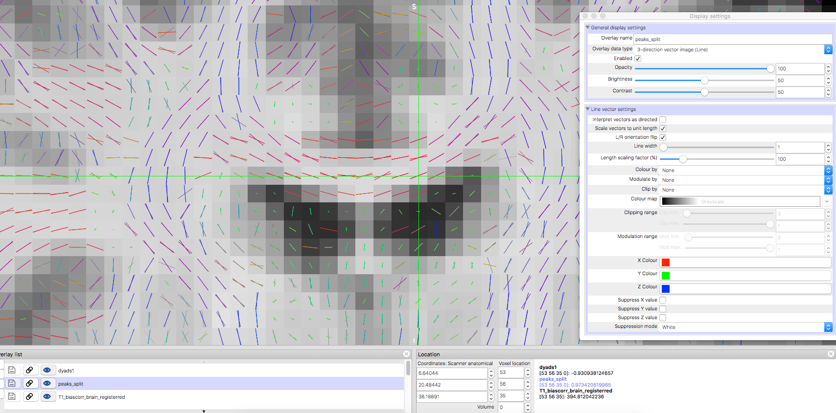
Open peaks in fsleyes looks incorrect
Open peaks in mrview looks correct
Open dyads in mrview looks incorrect
Also strange is that the recalculated peaks are looking like the same before.
So both programs work fine with their own calculated results.
But still a comparison in one viewer is impossible.
OK, now that’s very unexpected. If these problems are similar to what we faced before, you should find the behaviour is entirely consistent across both packages as long as the input data in encoded using LAS ordering (strides -1,2,3,4). Note that the raw DWI needs to be LAS, and all subsequent images should be regenerated from that. But if it’s still not consistent, then that’ll need further investigation. I’m on leave for the next couple of weeks unfortunately… The only thing I can suggest at this point is to try using an older version of FSLView - if I recall correctly, fsvliew 3.X worked as expected, fslview 4.0 didn’t, so we might get more clues by displaying the results with this version…
So just in case I did an update of Mrtrix to the newest version. But still got the same problems. I did some further investigations (see below) which in a way are interesting.
I also checked via mrinfo the -strides of the dyads/peak data and of the raw data.
Here are the outputs:
Image: “/Users/…/peaks_split.nii”
Dimensions: 112 x 112 x 62 x 3
Voxel size: 2 x 2 x 2 x 1
Data strides: [ -1 2 3 4 ]
Format: NIfTI-1.1
Data type: 32 bit float (little endian)
Intensity scaling: offset = 0, multiplier = 1
Transform:
1 0 0 -109.4
-0 1 0 -91.32
-0 0 1 -31.75
Image: “/Users/…/dyads1.nii.gz”
Dimensions: 112 x 112 x 62 x 3
Voxel size: 2 x 2 x 2 x 1
Data strides: [ -1 2 3 4 ]
Format: NIfTI-1.1 (GZip compressed)
Data type: 32 bit float (little endian)
Intensity scaling: offset = 0, multiplier = 1
Transform:
1 0 0 -109.4
-0 1 0 -91.32
-0 0 1 -31.75
the raw DWI also has the LAS ordering:
Image: “/Users/…/data.nii”
Dimensions: 112 x 112 x 62 x 204
Voxel size: 2 x 2 x 2 x 1
Data strides: [ -1 2 3 4 ]
Format: NIfTI-1.1
Data type: 32 bit float (little endian)
Intensity scaling: offset = 0, multiplier = 1
Transform:
1 0 0 -109.4
-0 1 0 -91.32
-0 0 1 -31.75
Also I found out that the new Fsl viewer called Fsleyes has the option to do a L/R orientation flip. When I turn this on, the peaks visualised correctly in Fsl. So I did some further investigation on the voxel values via matlab!
I took a voxel (see picture) of the corpus callossum where the orientation results of BedpostX (dyads) and CSD (peaks) are almost the same and opened the 4 dimension of the nifti files in matlab thus I could see the coordinate values.
So regarding to this I think already the calculated results differs from each other in their x-coordinate. Nevertheless both programs visualise their “own” orientations correctly and the “other” one incorrect. But this makes a comparison impossible.
So in this case not just the viewer interpretate the results differently also the calculations lead to inconsistencies. So would be nice if sombody could have a look on that.
Does anybody know if dyads in FSL are encoded in image space or scanner space? Because if the former (as they do with diffusion gradient directions), and you’re using a LAS image, this will produce exactly the effect you’re seeing. If you were to instead use a RAS image, the two results may or may not look identical, depending on the image header transform (the further away the transform is from identity, the greater mismatch between image space and scanner space axis orientations). You could experiment with different header transforms (the .mih format is excellent for editing image header entries) and axis rotations / flips to see if this is the case.
Unfortunately once you’ve got just a 4D image with three dimensions, you have no way of unambiguously knowing what reference axes those 3-vectors are defined with respect to. Hence why fsleyes has the L/R flip option. I suppose that from our end, we could have an option in mrview's fixel plot tool to invoke an imagespace-to-scannerspace conversion of the directions, if this is indeed the problem. But I’ve been known to be wrong from time to time.
So finally I could solve the problem! I splitted my 4d volumes into 3x 3d volumes and multiplicated the first volume which representing the x-coordinate with minus one. After that I re-concatenate the volumes to a 4d volume. Commands like fslswapdim or changing just the L/R convention didn’t achieve the desired results.
Maybe another important thing to call attention to was that the gradient values in the mif files are not the same as in the bvec files of the same diffusion data. The first row (x-coordinate) is multiplicated with minus 1! So I guess converting the nii data to a mif data which includes the gradient vectors an b-values is also changing the orientation?
OK, thinking about this some more, I guess what’s happening is that the coordinate system assumed by FSL is flipped L/R with respect to MRtrix3 (and hence with respect to the NIfTI standard, since MRtrix3 assumes the same standard as NIfTI). This wouldn’t be surprising, given that this is essentially the same convention as used to store their bvecs (i.e. the old ‘radiological’ Analyze coordinate system). On the other hand, the vectors produced by MRtrix3 will be with respect to the real space NIfTI coordinate system. I’m guessing FSL will produce vectors relative to the image’s own axes (as is the case with the bvecs), so that means you’ll probably find the coefficients are still inconsistent between MRtrix3 and FSL if the images are obliquely oriented… In short, I’d be very wary of converting these vectors between software packages.
Note that as you mentioned, each package remains entirely self-consistent - it’s just a difference in storage convention. Nonetheless, this could definitely lead to lots of confusion…