Dear MRTRIX community
I am trying to figure out how to convert tck files to mat to make them compatible with ExploreDTI. Does anybody know if there is a straight forward way of doing this?
Many thanks in advance
Vasilis
Dear MRTRIX community
I am trying to figure out how to convert tck files to mat to make them compatible with ExploreDTI. Does anybody know if there is a straight forward way of doing this?
Many thanks in advance
Vasilis
Hi!
did you manage to convert? if yes, could you please guide how you did it. Thanks!
There is a MatLab function within the code repository for getting contents of .tck files into MatLab. I however can’t comment on any esoteric requirements of ExploreDTI beyond that.
Rob
Hi Rob,
I managed to use the Matlab function to read the .tck file and have extracted the fiber index and 3d tract values. I am trying to align a muscle mesh (.stl) with the extracted fibres. Please correct me if wrong, the muscle mesh is already in mm and the fiber tracks values of .tck are also in mm? My T1-scan: 0.7x0.7x1 mm and Diffusion scan: 2x2x4 mm.
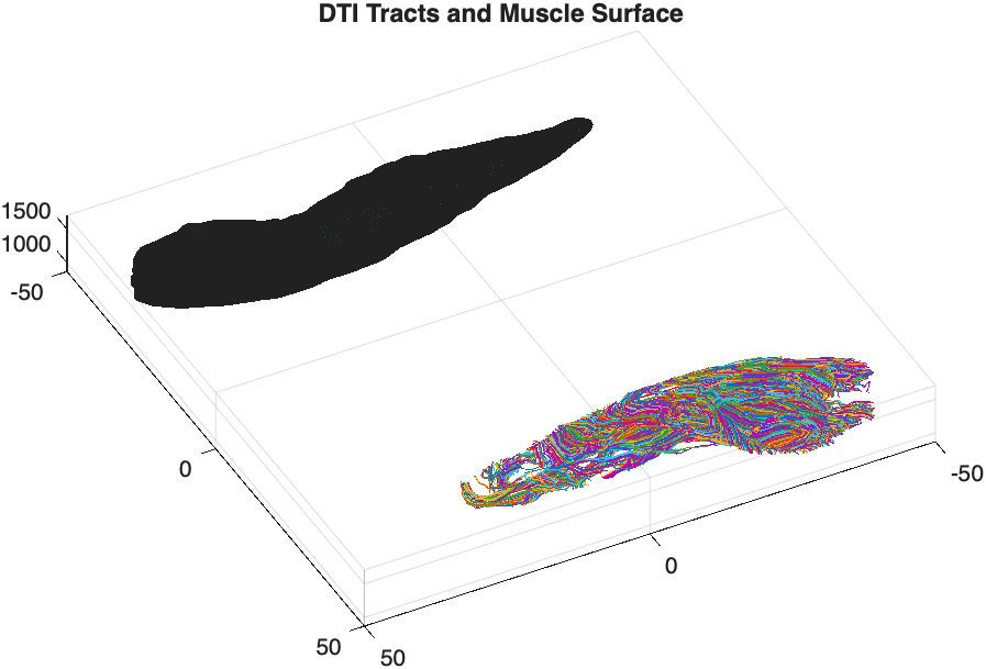
In the attached image, the muscle tracks and mesh are not in the same plane. Do I need to correct it only for registration i.e. scale, roatate or translate? or do I also need to do correction regarding the scan dimmensions? if yes, could you guide how to proceed?
I did ACT based deterministic tractography and I thought that the muscle mesh and the tracked fibres will automatically align, as I had already done the registration via FSL in mrtrix before performing ACT. But when I imported these in MATLAB, they both seem off.
Thanks!
Unfortunately there are far more ways that this can go wrong than there are ways in which it can go right. Stating that both datasets are “in mm” only guarantees that they are scaled equivalently; it says nothing about the origin that they define as [0, 0, 0], or the reference axes that each of the values in a triplet are defined with respect to.
You have not provided any information about how the muscle mesh STL was generated, so I can’t comment on how that may or may not align with streamlines generated by MRtrix. If that surface was itself generated using MRtrix using the voxel2mesh command, then its vertices should be defined within scanner / real space just as the streamline vertices are. You would need to look into whether eg. you may have generated that surface from the T1-weighted image prior to performing registration & transforming the image data from which it was computed, or erroneously run the meshconvert command and applied a transform. Or if you have generated that surface using some other software, then maybe it generates its vertices in voxel space rather than real / scanner space.
Hi @rsmith ,
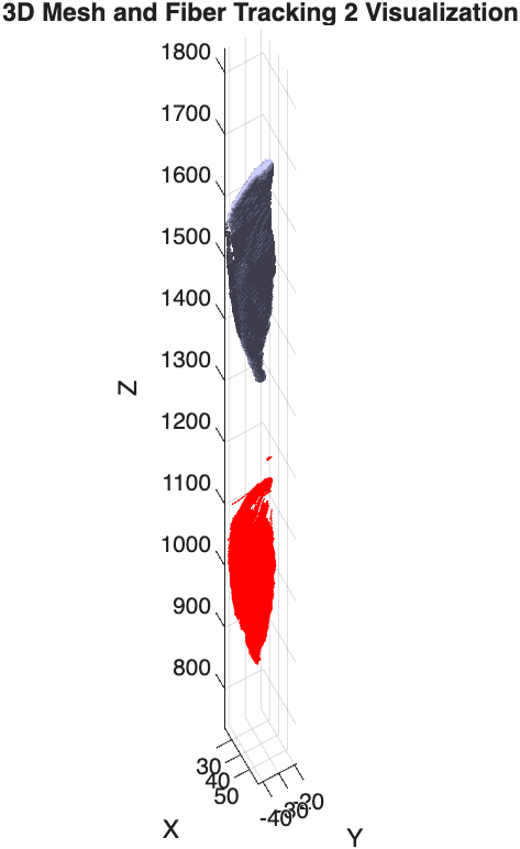
Thanks for replying. I looked into the .stl and the problem was that the file was formed in 3dslicer. Now, I used the mrtrix ‘voxel2mesh’ command to create the .stl file by applying the marching cubes algorithm. The fiber tracts and the resultant .stl file both seem to be in same scanner plane. But there is an offset (see in picture). My question is:
P.s. The resolution of my T1scan (.stl based) is 0.7x0.7x1 mm and the resolution of my Diffusion scan (.tck based) is 2x2x4 mm.
RAS Origin (voxel space)
T1: 251.4208, -145.7618, 792.600 mm
Diffusion: 206.5792, -147.8471, 324.1 mm
I would start by verifying that the DWI and T1-weighted image data overlap one another. If there is a massive offset between those two images, regardless of the origin of such an offset, then that’s the point of intervention; trying to diagnose anything based on tractogram and surface data is just confounding diagnosis.
The concept of “resolution” is different for tractogram and surface data than it is for image data. One could conceivably make the argument that while for image data, “resolution” refers to the spacing between voxels, for tractograms the distance between vertices along a streamline (more commonly “step size”) serves a similar purpose, and for surface data the typical distances between adjacent vertices serves a similar purpose. However from your description I don’t think you’re actually trying to make this point. I think more likely there’s a fundamental misunderstanding of the nature of the data at hand.
A difference in image resolution should not result in an offset in space. We very frequently have DWI and anatomical data of different spatial resolutions that overlap in realspace. However if there is some deficiency in upstream image encoding or manipulation—perhaps something like assuming that voxel [0, 0, 0] sits at location [0.0, 0.0, 0.0]—then a difference in spatial resolution could manifest as an offset in realspace between image content. But this needs to be diagnosed and rectified in the source image data, it’s not an issue of how tractogram and surface data are encoded.
For MRtrix3, both streamline vertex locations, and surface vertices, are defined in real space, and are not intrinsically tied to any specific voxel grid. There should therefore not be any offset in their position, if the image content from which each was independently generated already overlapped in realspace. If those images don’t overlap, then deal with that problem first.
How do I take care of the resolution of the tck file? I think I can’t downsample it.
Tractogram files do not have a “resolution” as do image data. You can do resampling of streamline vertices based on a continuous spline representation of each streamline via the tckresample command. But I think this question is not aimed at that interpreation but is rather indicative of a misunderstanding of the nature of these data.
My end goal is to calculate the fiber lengths. To do so, it ll be imp to have it in the same size.
Streamline lengths can be computed using tckstats. This is based on summing inter-vertex distances in real space. I’m not sure how you may have envisaged computing streamline lengths in a manner that is predicated on the resolution of an image voxel grid.
The .stl mesh obtained via mrtrix have a region with big hole inside. is there anyway that I can fill this hole? The .stl obtained from the 3dslicer had no holes.
The surface manipulation capabilities of the software remain somewhat limited. But the holes won’t be there arbitrarily, it will be areas within the structure where the intensity is lower than the surface-forming isocontour level, and 3dslicer will be doing something explicitly to remove them.
P.s. The resolution of my T1scan (.stl based) is 0.7x0.7x1 mm and the resolution of my Diffusion scan (.tck based) is 2x2x4 mm.
I would say that the .stl is T1w-based and the .tck is diffusion-based, not the other way around.
Regards
Rob