I am a beginner when it comes to analysing MRI, and I’d like to ask you guys some questions. A colleague has tasked me to produce some NIFTI files from 2dseqs using Nanconvert, and so I did. I now have the .nii, .bval and .bvec files for all the animals I need to analyse.
I used one of the .nii files she previously converted and explored it to check that orientations and bvals/bvecs of the files I produced are correct, however the orientation of the ones I created are incorrect (see pictures of the one she made [proper orientation] vs the one I made [all over the place]).
She had a look at the data and said the bvals and bvecs were ok despite the orientation, and that I could correct the orientation using mrtransform or mrconvert. I have read the documentation regarding both and I’m still unsure which one should I use and why. May I ask some questions?
-Which function would you use to change the orientations of the files to make the “distorted” one looking like the one she made?
-How do I check the bvals and bvecs have not been messed up with this reorientation?
-The examples in the documentation all use a .mif file (which according to my colleague contain the bvals and bvecs embedded in the file itself). This means I’ll first have to create the .nii files. Would this command work?
I’d never heard on this tool, but I note this is one of Toby Wood’s. Might be worth getting in touch with him directly to enquire.
I might get in touch with him too to figure out how he does his Bruker import. We provide the convert_bruker script to do this, but it’s not perfect (we don’t yet deal with the slice orientations properly).
What I am surprised by though is that your converted data look like they’ve either been regridded, or they’re being displayed off-axis. What software are you using to display these data? And what do they look like in mrview by default?
Before offering any suggestions, I’d like to know whether this is actually necessary, which means inspecting the data in mrview. There’s a chance the data are actually simply being displayed off-axis, rather than requiring any particular manipulation.
yes.
Yes and no. It depends exactly what might be needed to fix the problem. If it’s a simple rigid body transformation, with no regridding, you might be fine to stick with the bvecs/bvals (though there’s a few things to watch out for in the process) – but using the mif file as input will also work correctly. If it does involve regridding, then I would recommend converting to mif first. So in both cases, the safest option is probably to use mif as your input format, since this should work correctly regardless.
Yes, I’m the author of nanconvert. It looks to me like you are using fsleyes to view the data, and nanconvert thinks that the acquisition was oblique.
Was the acquisition oblique? If it is possible to share the data I can investigate further. It might be worth opening an issue at https://github.com/spinicist/nanconvert/issues as this isn’t really an mrtrix problem.
PS: Sorry about the double post but since I can only attach one picture to a reply, I had to create another reply.
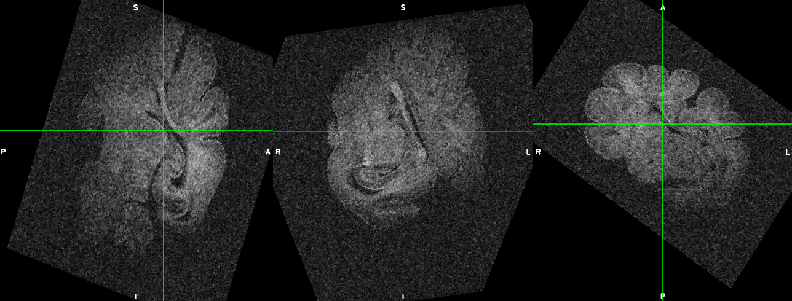
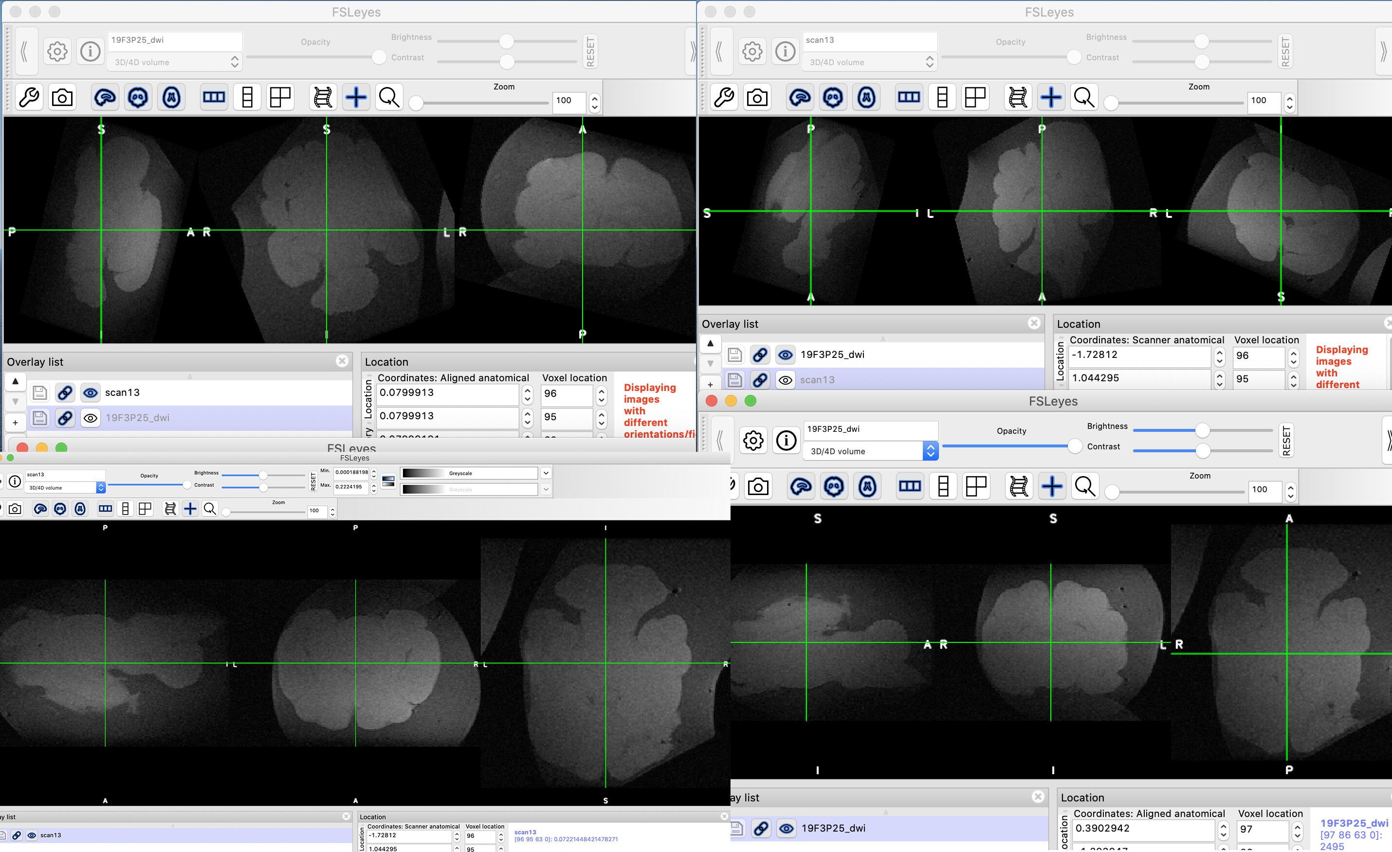
This might interest you as well. When I drag and drop the niftis into a fresh fsleyes windows, the orientations are fine, but when I drag and drop it into a fsleyes windows that has another scan opened, the second scan orientations appear distorted, regardless of whether it’s my nifti or hers being used. And I have no idea why this happens. See below for some screenshots. Bottom: my file (left), her file (right). Top: my file dropped after hers (left) and her file dropped after mine (right).
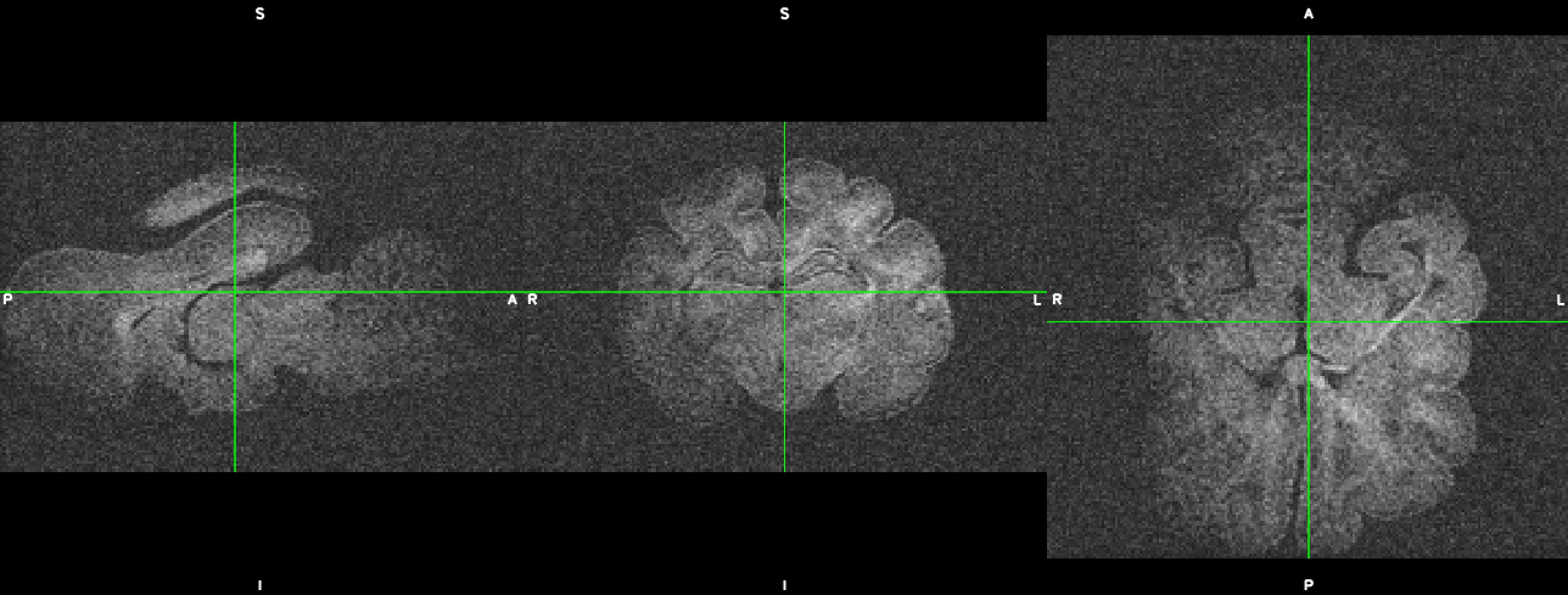
Hi guys =) thanks so much for your answers. I’m attaching the pictures of one of my scans as viewed in fsleyes and mrview. Since I’m new to MRI and to coding, I don’t know what happens under the hood. And since I wasn’t the one doing the acquisition, I don’t know if the acquisition was oblique. I am happy to share my data if you need me to =)
This is how the data looks in fsleyes for the nifti file my colleague provided me (top left) and the one I generated (bottom left), and in mrview (hers in top right and mine is bottom right). I just drag and drop into fsleyes and mrview. She told me she used nanconvert on the 2dseq to create the nifti, and she didn’t mention anything regarding having to correct orientations, and she was also surprised that I got these strange orientations.
Now that I look closely, even on her data the AP and SI axes are wrong, and will probably need to be corrected. But that doesn’t explain why they look so different in both fsleyes and mrview, and why hers looks different to mine even when supposedly they came from the same raw data and using the same script.
In the end, I just need to correct the orientations so I can register the whole group of animals (ferrets in this case, I also have to work with sheep and mice), and then perform DWI analyses, as I need to extract FA, RD, AD and MD values from all these scans.
Thanks for your help and let me know if you need my data shared, and what files do you need me to share.
Hello,
there’s a few different things going on here, so I’ll try to break it down.
1 - I think the original problem you reported, with the images appearing rotated in FSLeyes, is to do with opening extra images in an already open FSLeyes instance (from what you’ve said about drag-and-dropping images). I have seen FSLeyes do funny things with changing the display orientation when opening extra images. I’ve never seen rotations like that, but I have seen flips. If you can find a set of steps that can reliably produce this problem it is worth reporting to the FSLeyes maintainer (https://fsl.fmrib.ox.ac.uk/fsl/fslwiki/FSLeyes#Help_and_troubleshooting, he’s very friendly).
2 - FSLeyes and MRview are actually showing the same thing. The important thing is to look at the labels (S/I, A/P, L/R), and how they compare to the anatomy, which match in your screenshots. This is re-assuring. Yes, they do visually appear different. Image viewers are free to choose which screen direction to use to represent anatomical directions. In this case FSLeyes and MRview are using different display conventions. If you press the Wrench button in FSLeyes there is a “Display Space” option where you can pick between the data/voxel space and “World Co-ordinates”, you may find the latter more intuitive (I do).
3 - That leaves your converted image having different anatomical labels to your colleague’s converted image. Are you sure your colleague did not do anything that could alter the nifti header, e.g. registration? Are you using the exact same version of nanconvert? How did you obtain nanconvert, did you compile it yourself?
I obtained nanconvert by following the instructions provided in the nanconvert website. I downloaded ITK and CMake from their respective websites and installed it using the provided instructions in the documentation to the best of my abilities. I don’t believe there was any error in the installation process but if you tell me where to look for I can go and do this. So I guess the answer is yes, I did compile it myself, but I’m not sure since I’m new to coding so I’m not entirely sure what “compiling” means which is different from “installing” it. I have records of the commands I used to install both ccmake and ITK so I can provide them if needed.
Thanks for your comments on the orientation issues in fslview, I’ll definitely report the issue to them. However I am still left with how to perform the changing of the orientations of the scan.
Let’s say after I used nanconvert the AP/SI/LR orientations are wrong in either fslview or mrview (either inverted in the correct axis [AP anatomy shows A label in P and P label in A] or in the wrong axis [AP anatomy displays LR or SI labels]), how do I fix that without making a mess of the bvals/bvecs?
Can this be done with additional input to nanconvert or is this doable with mrconvert?
That’s the correct way to “install” nanconvert. There is a possibility that your colleague compiled an older version and there’s a difference in orientation handling between them, but I can’t see anything in the git history to suggest this. It’s been a couple of years since I wrote that code. Sorry not to have a better answer as to what is happening.
I have (I hope) only one last couple of questions regarding this thread. I have read the documentation for mrconvert, and as suggested above the -axes option might do the trick, although since I am not too familiar with the tool, I am unsure what values to input, or where. I know the first three numbers of the command reflect the three spatial axes of the image, but I don’t know:
-What number is what axis (e.g. 0,1,2,3), and
-What values to input for, say, inverting the axis (e.g. AP to PA) or assigning another axis (e.g. changing AP for SI if needed). I am afraid this is not part of the documentation (or at least I couldn’t find it).
-Additionally, if I wanted to make no changes to an axis, what value should I input? 0?
Thanks for your time and patience! Most appreciated =)!
Correction: Using a value of -1 in the input to mrconvert -axes actually inserts a new axis of size 1 (mrconvert help page example usages).
The ways that you can proceed are:
(hard) Using mrtransform, provide a rigid body transformation that, either through application to the existing image header transformation or by replacing said transformation, results in the correct attribution of image axes to spatial orientations.
(easy) Split into two steps:
Axis permutation: Use the mrconvert -axis option. The values that you put into the comma-separated string after “-axis” are the axes of your input image (where 0 indicates the first axis), and the order of those values are the order in which you want those axes to appear in your output file. Any axis for which its position in the order is equal to its value (remembering that counting starts from zero) will not be changed.
This tends to be easier to just try all possibilities and pick the correct one rather than trying to figure it out. But don’t worry about the direction of each axis, just make sure that the three axes orientations are correct. Chances are you don’t want to permute the axis corresponding to volumes, so the fourth entry in the axis list should be 3.
Axis flipping: Use mrtransform -flip. Same as above, 0 corresponds to the first image axis (which should hopefully be L-R or R-L following the first step. Provide a comma-separated list if you have more than one axis that needs flipping.
I am afraid this is not part of the documentation (or at least I couldn’t find it).
If axis permutation had been included as an example usage for mrconvert, and the corresponding explanation directed to mrtransform flip, would you have found it there? If not, it might be a good candidate for a Wiki entry.
Thanks, Rob and sorry for the confusion (I find the -1 for inserting a new axis is somewhat counter-intuitive). By the way, mrconvert’s way to flip data as hinted at in the first sentence of its description is via -coord 0 end:0 (LR flip) but that does not modify the gradient table so shouldn’t be used here.
go to Tools --> Transform, toggle the switch to on
move / rotate the main image until the orientation labels match the image
File --> save as dwi_rotated.mif
Note that the gradient table in dwi_rotated.mif is not modified. Hence, we extract the transformation, make sure it’s rigid, and apply it to the image which takes care of the gradient table reorientation:
Yep, I know what you mean. But it was the simplest solution to allow inserting missing axes in the rare cases where that might be required (typically to convert a 3D image to a 4D, single volume image, using e.g. -axes 0,1,2,-1.
I suppose we could come up with some enhanced syntax to allow missing entries in these integer sequences (e.g. for the example above, -axes 0,1,2,, which matches the floating-point version, or -axes 0,1,2,x or something), but that would require a few changes in the backend. Worth discussing on GitHub if there’s demand for it.
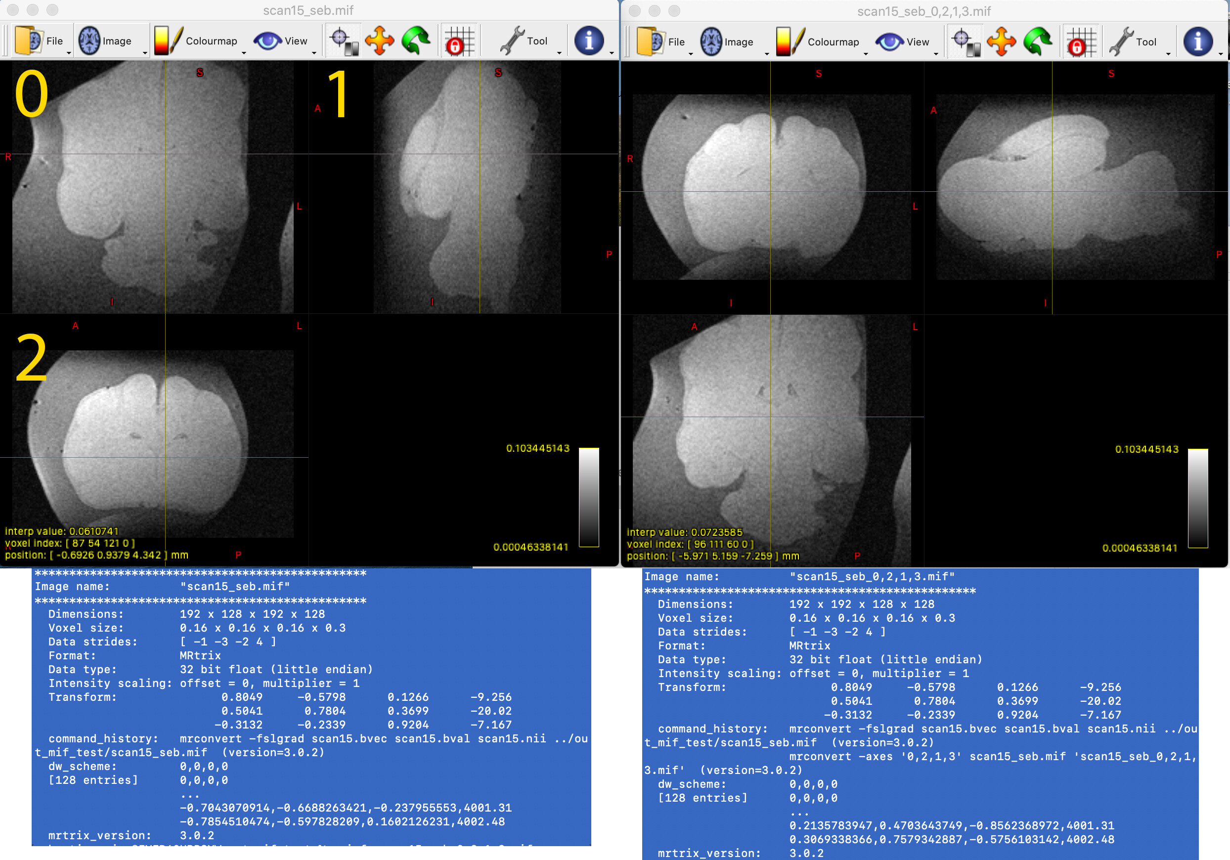
Thanks guys for your help!! I managed to get what I wanted using what Rob suggested by first permutating and then flipping (although I found that I didn’t need to flip on this scan, but might need on others).
After reading the documentation for mrconvert, I tried the permutations based on the examples and info. It says that “MRtrix3 uses a RAS (Right-Anterior-Superior) axis convention, and internally reorients images upon loading in order to conform to this as far as possible”, so I assumed that axes 0, 1 and 2 were axes LR, AP, and SI respectively. However when I went and used the -axes option, I found that the transformation that worked was -axes 0,2,1,3 . See below the image from the original (left) and the reordered (right). I overlaid the numbers of what I thought were the axes in the input as presented by mrview:
This was however not what I expected (or maybe I am understanding mrtransform and mrview all wrong. I thought -axes 2,1,0,3 would have worked since that’s what I assumed I was reading on mrview on the original scan (left), and then to create the final file (right) I needed to put 2 first, then 1 and then 0, while in fact 0,2,1 was what worked.
Am I reading the axes numbers wrong in mrview? If so, what is the correct way to read them? I’m asking so I know what numbers and what order to input for the next scans that I need to transform.
Well, looking at your images, it looks like the original IS direction axis maps onto the AP axis, and the AP onto the IS, leaving the LR unchanged. So your new axes should correspond to what was originally the LR, IS, AP axes, in that order – i.e. 0,2,1 (or equivalently: x,z,y). Hope that makes sense?
What I would recommend you double-check though is whether you also need to flip the x axis. By switching the y & z axes around, you’ve effectively mirrored the images through a plane oriented at 45° through the axial plane. That will probably have changed the handedness of the coordinate system, leaving your LR axis inverted relative to what it should be. I would recommend you try to find some independent way of verifying left & right for your scan – this is often the trickiest one to get right, and easily overlooked, but that can have some fairly nasty consequences downstream if you’re not careful…
Yes, That makes sense. I’ll keep this in mind to save myself the trial and error when swapping axes.
Funny you mention that, because I did perform an X flip using mrtransform -flip 0 and compared both flies and I really couldn’t tell any substantial difference between the two. I felt like I was looking into the brain in a mirror, but still making sense at the axes levels. From your experience, what would you recommend in terms of an “independent” way to check left and right in the scan? Since the brain is highly symmetric (and this is even more so in “simpler” brains like sheep, ferret and mice which are the ones I work with right now), I am not surprised by my inability to tell whether the mirrored image was the correct one or not.
That’s precisely the problem… Now imagine knowing your code is to be used for human brain surgery, and you’ll appreciate the need for a certain fixation on getting this right…
Check your output against what the scanner shows on the console. Find a feature that allows you to tell the difference (maybe the brain is slightly tilted, or one of the hemispheres is bigger, or the ventricles are bigger on one side, etc), and compare. Make sure you also triple-check how the scanner displays left & right: on a human scanner, they’ll always be displayed using radiological convention, with patient left on display right (same as mrview), hopefully it’s the same on your scanner…
Thanks for this =) I didn’t perform the scan myself, so I’ll ask my colleague and maybe we can find something that tells us orientations to check if a flip is needed.
Great! Thanks for this =) I might give it a go and install this to check if it behaves differently to the one I compiled.