Greetings MRTrix community and experts! This will be my first post, first of many I would assume ![]() .
.
I want to start of by giving some background about my knowledge of the area: at the moment of writing this I have finished my 4th year as a master student in engineering physics although I have taken some courses in biomedical engineering and read some papers regarding this topic, thus my knowledge of the brain is fairly limited.
Nevertheless, we all start somewhere and this far I have completed the MRtrix tutorial provided on Andy’s Brain Book and I am now in the middle of trying to replicate the process on data for a research project regarding MRgFUS that I am working on, thus the DRTTs are the tracts we at the moment are trying to delineate.
The DWI-data is gathered on a 3T GE-scanner, it is multi-shelled with shells: b=0, b=1500, b=3000 [s/mm²] of dimensions 256x256x82x102 with voxel size 1x1x1.8x4.961, I am using MRtrix version 3.0.5.
Now regarding my question, I have estimated the RFs using the “dwi2response” command with the “dhollander” algorithm, running the command:
$ dwi2response dhollander DTI99_den_preproc_unbiased.mif wm.txt gm.txt csf.txt -voxels voxels.mif
I include below the information provided by the command regarding the process
dwi2response: Computing brain mask (dwi2mask)…
dwi2response: -------
dwi2response: 3 unique b-value(s) detected: 0,1500,3000 with 9,47,46 volumes
dwi2response: -------
dwi2response: Preparation:
dwi2response: * Eroding brain mask by 3 pass(es)…
dwi2response: [ mask: 997220 → 819087 ]
dwi2response: * Computing signal decay metric (SDM):
dwi2response: * b=0…
dwi2response: * b=1500…
dwi2response: * b=3000…
dwi2response: * Removing erroneous voxels from mask and correcting SDM…
dwi2response: [ mask: 819087 → 817679 ]
dwi2response: -------
dwi2response: Crude segmentation:
dwi2response: * Crude WM versus GM-CSF separation (at FA=0.2)…
dwi2response: [ 817679 → 480619 (WM) & 337060 (GM-CSF) ]
dwi2response: * Crude GM versus CSF separation…
dwi2response: [ 337060 → 247876 (GM) & 89184 (CSF) ]
dwi2response: -------
dwi2response: Refined segmentation:
dwi2response: * Refining WM…
dwi2response: [ WM: 480619 → 437185 ]
dwi2response: * Refining GM…
dwi2response: [ GM: 247876 → 166875 ]
dwi2response: * Refining CSF…
dwi2response: [ CSF: 89184 → 56748 ]
dwi2response: -------
dwi2response: Final voxel selection and response function estimation:
dwi2response: * CSF:
dwi2response: * Selecting final voxels (10.0% of refined CSF)…
dwi2response: [ CSF: 56748 → 5675 ]
dwi2response: * Estimating response function…
dwi2response: * GM:
dwi2response: * Selecting final voxels (2.0% of refined GM)…
dwi2response: [ GM: 166875 → 3338 ]
dwi2response: * Estimating response function…
dwi2response: * Single-fibre WM:
dwi2response: * Selecting final voxels (0.5% of refined WM)…
dwi2response: Selecting WM single-fibre voxels using built-in (Dhollander et al., 2019) algorithm
dwi2response: [ WM: 437185 → 2186 (single-fibre) ]
dwi2response: * Estimating response function…
dwi2response: -------
The RFs looks reasonable to me, the volumes are shaped as I would expect with the WM showing a clear anisotropic behavior for non-b0 values and GM/CSF being isotropic, their magnitudes decreasing with increasing shells. I would provide an image but it seems as a new user I could only include one and I believe the RFs can be described by their parameter values instead:
WM:
4801.50950503143 0 0 0 0 0
2275.33020633093 -1125.49358817565 371.228823973852 -79.9636359452689 8.53893164983394 0.722755748079911
1604.07770671768 -932.78442680307 503.157969439236 -195.247110095876 52.3921839876302 -8.5322801271091
GM:
7769.72345594421
2508.93076132426
1080.33320268872
CSF:
16697.4317257711
303.518197070762
241.140721262514
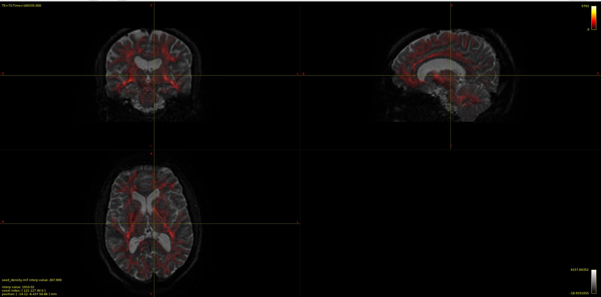
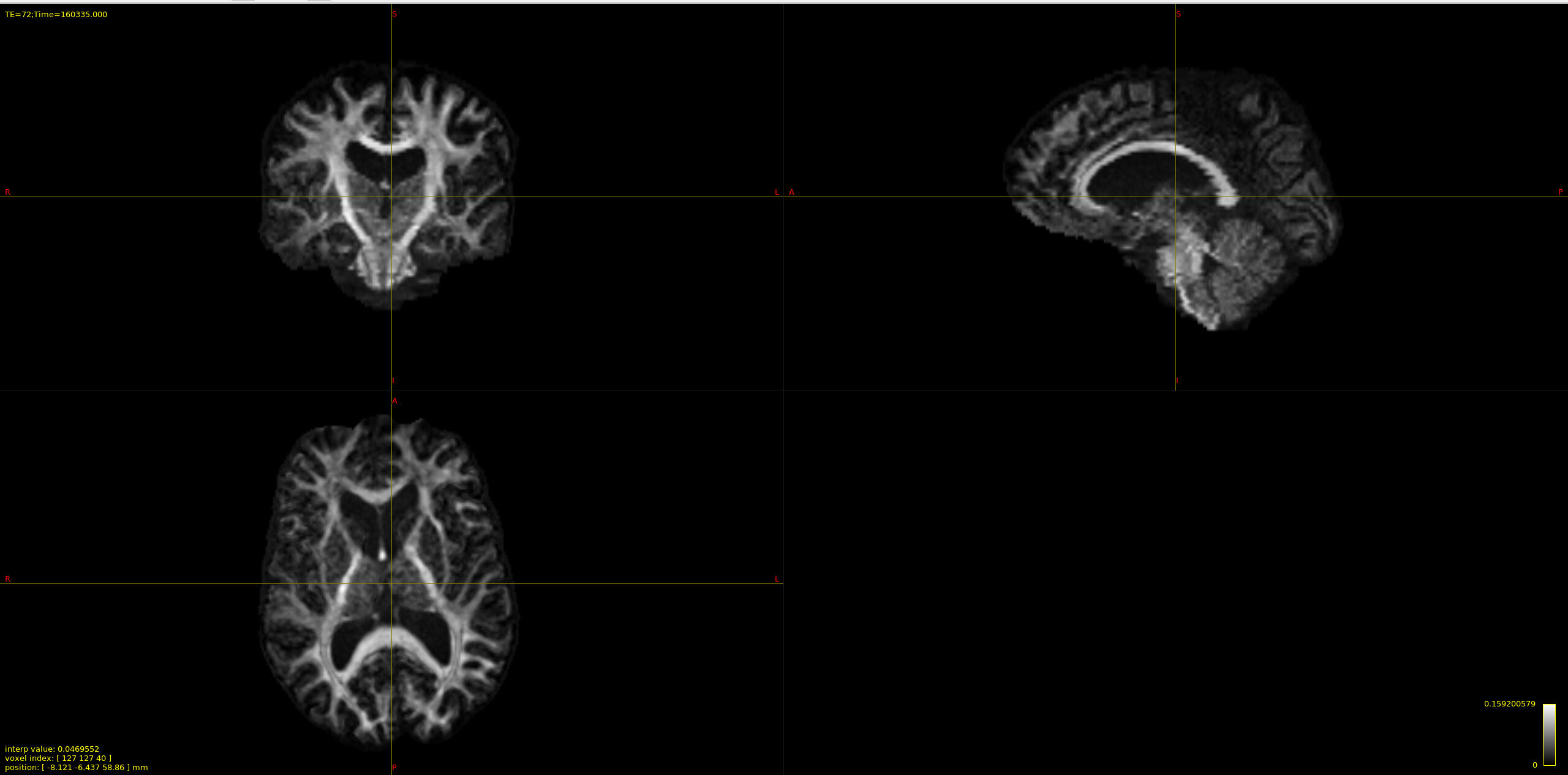
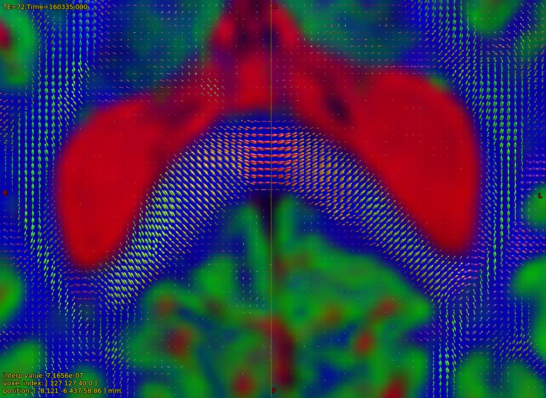
Now my question is regarding the chosen voxels for the estimation, I provide the image below overlayed on the b0 DWI image:

and that which seems strange to me is the CSF voxels, specifically that none seems to be taken from the ventricles, which to my understanding should be the location of most representative CSF voxels of free diffusion. As I have understood, the dhollander algorithm leverages no anatomical information but instead chooses voxels based on how well they represent the expected characteristic diffusion signal of that tissue. So maybe this is not actually a problem since the RFs looks good, but I wonder what it says about my data if the most representative CSF voxels are not located in the ventricles, is it down to partial-volume-effects, or is it expected behavior?
Kind regards,
Andreas