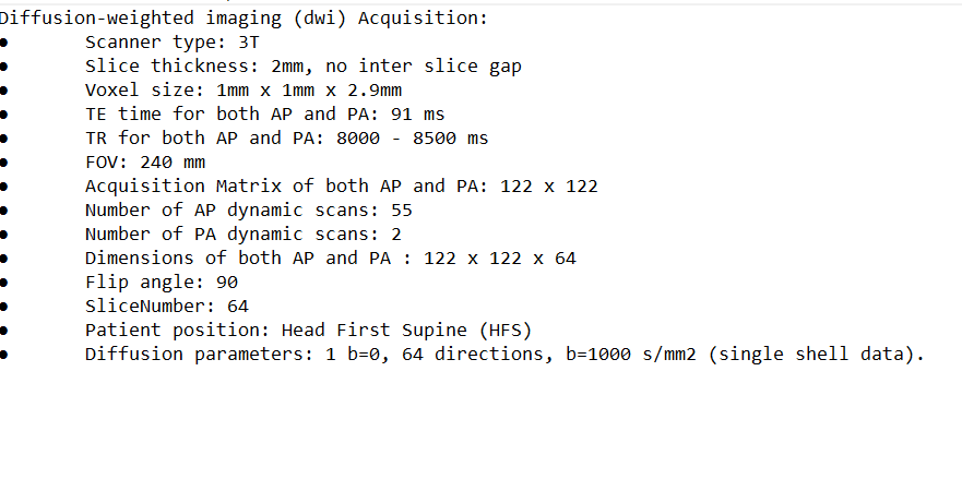
I am working, on the DWI data taken from the GE 3T scanner and after running the complete pipeline up to tcksift, the results are not good for clinical purpose, I am attaching all the relevant information, along with the DWI protocol, we are acquiring only single B0 image (only the first image), and rest all have the b0=1000, voxel size of 1x1x2.9.
Please find the attached screenshot, of the output of tcksift algorithm, I ran, dwidenoise, mrdegibbs, dwifslpreproc, biascorrection, dwi2response, dwi2fod, mtnormalise,Processing: dwi protocol.txt…
Getting decent data on GE scanners can be tricky due to their tendency to apply zero-filling interpolation by default, with no simple way to disable it. I expect that would be the primary issue with your data: your acquired voxel size clearly isn’t actually 1×1×2.9mm, since your acquisition matrix is 122×122, which would imply a field-of-view of 122×122mm and that wouldn’t be sufficient to cover the brain. I suspect that the scanner has zero-filled your data to 256×256, which you can verify with mrinfo.
Besides, you state a slice thickness of 2mm with no slice gap, yet the voxel size comes out at 2.9mm along the z-axis, which isn’t consistent with that. I would recommend you try to get an isotropic 2×2×2mm voxel size, potentially higher than that if SNR is poor (e.g. 2.3mm isotropic).
Assuming your data have been zero-filled, my first recommendation would be to disable that. Unfortunately, the last time I looked into this, it wasn’t easy. Others on this forum may be able to help here, but I think the process was to set the image size to the same dimensions as the acquired matrix size (in your case, 122×122), but that setting was not easy to find (might even require research access).
Other than that, my recommendation would be mostly to increase the b-value to at least 2,000 s/mm² (preferably 3,000 s/mm²). And figure out why the slice thickness doesn’t match with the voxel size…
Indeed, you will need to disable interpolation. By default, GE scanners interpolate to 256x256.
So, you will need to ask a GE Apps Specialist to provide you with a research key. Once the scanner has a research key, you ‘Download CV’, type in rhimsize, and set the matrix to your matrix size which in your case in 122. After that, the reconstructed matrix will be 122 x 122 i.e. no interpolation.
Sorry for responding late, I was working on the solution that you provided, and nothing solved the issue, we set the matrix to 122 with the help of the research key, but that could not solve the issue, I am attaching the latest JSON export from the recent protocol.
From my recollection, the research mode user interface of GE is extremely finicky.
To select a research variable, you have to type its name and then press “enter”. If you do not press enter first, any subsequent value you type in for that variable will have no effect …
Also, once you have managed to properly select a certain research variable and you have typed in a value, again you have to press “enter” or the research variable will not be set successfully.
On top of this, all of these steps you have to perform with zero feedback from the GUI, so it is extremely easy to get things wrong…
To make sure that your new matrix has been set correctly, do what you have done (changing rhimsize, press Enter etc), then close the table. Then repeat the Download CV, Display CV procedure, and then check that rhimsize is 122.
Thank you, Jerome and Ben for the advice I will make the necessary changes as it was suggested by you, one more thing I would like to clarify is GE application mentioned to us that. they could not take more than one B-value ie they will only be able to take 0 and 1000, is it possible or it is just an incomplete knowledge?
Hi again
I have another concern regarding GE DTI. I do not get any slice timing in the json-file, as I a matter of fact dcm2niix explicitly states that it cannot provide slice timing. I look in this link dcm2niix/README.md at master · rordenlab/dcm2niix · GitHub
and understood that GE poorly provides slice timing for DTI. None of the DICOM tags suggested in the link had any viable informationen. Thus, does anyone know how to get slice timing provided in the json-file for GE DTI. I use a Discovery MR 750 with 25\LX\MR Software release:DV25.0_R02_1549.b.
My name is Nick and I work with DTI in Sweden, also using GE. I don’t really follow why reconstruction to 256 should have any effect on further preprocessing of the DTI data and the look of the tracts? I have seen similar reconstructed images many times and the tracts look fine. Could you please elaborate on the effect of reconstruction?
Is your primary source of concern that of geometric distortions? If so, while many of the comments may be relevant for your data, they’re not actually addressing your question (which is why it’s beneficial to be specific about such concerns). It also means that anything after dwifslpreproc is potentially a red herring.
There is however one further peculiarity in your data exposed by showing streamlines, which somehow nobody else spotted. You DWI gradient table is incorrect. You have green streamlines traversing anterior-posterior in the middle of the corpus callosum. Suggest running dwigradcheck to see the likely issue (and chasing up from the data source to try to find where something has gone wrong). There’s some chance that an incorrect gradient table may lead to poor pre-processing, but it depends on the internals of how FSL’s eddy works. Following replacement of the gradient table with the estimated correct one, make sure to check the FODs estimated by CSD; the error should have been relatively clear from showing those.