Eddy Current still visible after dwipreproc analysis

Dear MRtrix experts,

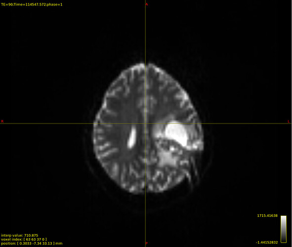
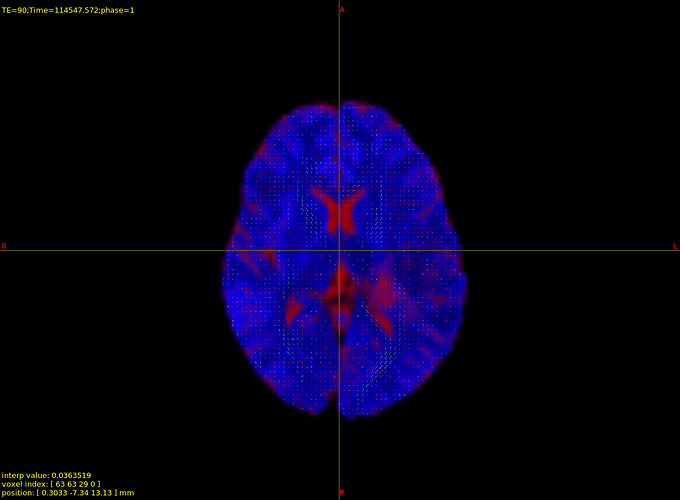
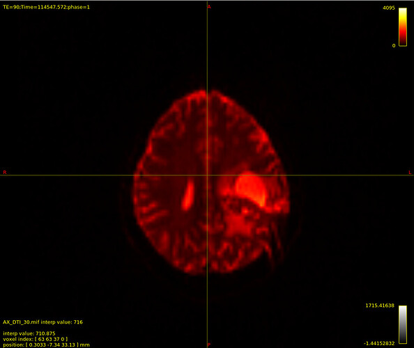
I have done dwipreproc on my DTI dataset. However, I see no change between my original and processed DTI images. The eddy current is still visible in the image. I’d appreciate any advice you might have on this matter. Also, according to MRtrix tutorial, I was expecting this line of command take hours to run. However, for me it took less than 15 minutes to complete the process. I have attached photos for your review. The red color is the original DTI image, and the black and white image is the corresponding processed image.

Thanks

Hi,

I’m not sure I’m seeing what you mean when you say ‘the eddy current is still visible’. I don’t see any particular suggestion of eddy current distortions here? Do you mean susceptibility-induced distortions? If so, I expect the issue is that topup is unlikely to be able to correct what look like very strong distortions near that lesion – which I expect are caused either by an open skull or a metal plate on the skull?

Cheers,
Donald.

Just to go over a couple of points I’d overlooked:

Runtime depends heavily on the availability of a CUDA-capable GPU – i.e. a NVidia graphics card. If you have one of those on your system, runtimes of 15 minutes are in line with expectation.

Otherwise, looking at your other recent posts, it seems your data has a single phase-encoding direction? In which case there is no data for topup to estimate the distortions from, and no scope for correcting susceptibility-induced distortions (which I assume is what you’re concerned about here).

Hi Donald,

Thank you for your response. I thought this effect is eddy current since it’s changing from one volume to another. In some volumes, specially b=0, it looks more significant. It’s true that our data is acquired with single phase-encoding direction. That’s why I skipped the step " Extracting the Reverse Phase-Encoded Images" in MRTrix tutorial. It’s good to know that this effect is susceptibility-induced distortion. As far as I understood, there is nothing I can do about it at this point. I hope this effect doesn’t negatively impact my whole analysis.
Now I am facing another barrier in Fiber Orientation Density and Normalization section. :confused:/
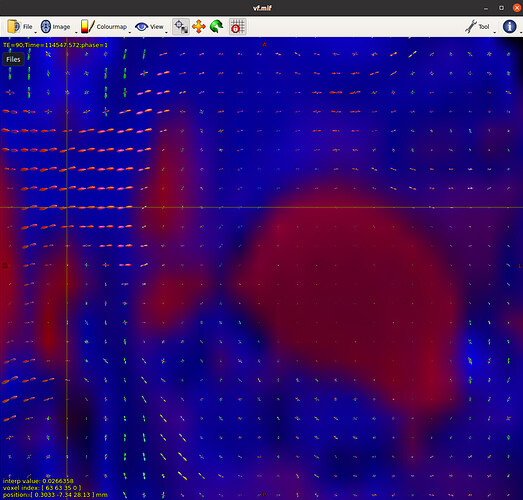
When I look into vf.mif, I don’t see any gray matter information (green colour). I am not sure why!
I have attached image for your review. As you can see, there is a little bit of fiber tract information inside csf!

Also, when I run normalization command, I receive the following error: mtnormalise: [ERROR] Non-positive tissue balance factor was computed. Balance factors: -nan -nan -nan

I’d appreciate any guidance or solution you might have on this matter.

Parand

Hi Parand,

However, I see no change between my original and processed DTI images.

Rather than looking at the two images separately, or in two different windows, are they precisely numerically equivalent? You could also have a look at the motion / eddy current parameters estimated by eddy (they’ll be in the scratch directory if you run dwifslpreproc with the -nocleanup flag), to see if there is in fact genuinely zero correction being applied.

As far as I understood, there is nothing I can do about it at this point. I hope this effect doesn’t negatively impact my whole analysis.

SynB0-DISCO is worth attempting. I’m sure @schilkg1 would appreciate feedback on its operation in the presence of such lesions!

Now I am facing another barrier in Fiber Orientation Density and Normalization section. :confused:/
When I look into vf.mif, I don’t see any gray matter information (green colour). I am not sure why!

I assume “vf.mif” is supposed to be “volume fractions”; not actually sure which document you are working off. But I’m guessing that you have single-shell data, in which case dwi2fod msmt_csd cannot estimate a three-tissue decomposition because there are only two unique b-values (admittedly it would likely be preferable for the command to generate an appropriate error message under such circumstances).

As you can see, there is a little bit of fiber tract information inside csf!

You can’t necessarily expect the WM ODF to be of exactly zero magnitude inside of regions that are otherwise considered to be CSF; there’s both the prospect of there actually being some restrictive structures in some such regions, and the possibility of image noise making the diffusion-weighted signal look like CSF with just a smidgen of WM rather than being a perfect match to the CSF response function. Indeed if you were to consider the limit where the CSF response function is based off of the most extreme exemplar CSF voxel, then every voxel other than that one exemplar voxel would have a non-zero WM ODF.

Also, when I run normalization command, I receive the following error: mtnormalise: [ERROR] Non-positive tissue balance factor was computed. Balance factors: -nan -nan -nan

This may be related to having provided the empty GM ODF to mtnormalise. If you re-run mtnormalise using only the two valid ODF images, and still run into this problem, there are a number of threads on the forum that go through the debugging process for this specific error message.

Cheers
Rob
A post was split to a new topic: Streamlines crossing through tumour