Hi, I am a bit new to this software. I was wondering if someone could help me with the response function using tournier for e.g. I have tried following the instructions on the mrtrix3 page. But I dont get some parts.
For.e.g
It says
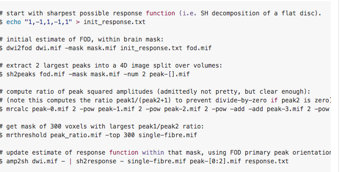
Select the 300 ‘best’ single-fibre voxels. This is not precisely the ratio between tallest and second-tallest peaks; instead, the following equation is used, which also biases toward selection of voxels where the tallest FOD peak is larger: sqrt(|peak1|) * (1 - |peak2| / |peak1|)^2. Use these voxels to generate a new response fuction.
Test to see if the selection of single-fibre voxels has changed; if not, the script is completed.
What code would I type in?
I did some research on the internet and came across this…
Is this right? Is there like a manual/video which goes slowly through doing tractography in terms of the coding.
I think you have been making your life a bit harder than you needed to… the dwi2response script handles all of this. You should be able to do all this with a one-liner as in the documentation. Full details on response function estimation on this page. Hopefully that should clarify things…?
I think you’ve misunderstood the contents of the response function estimation page in the documentation. There I describe the operation of the response function estimation algorithms that are provided as part of the dwi2response script; i.e. those are the steps that the script is performing internally to achieve response function estimation.
If you are simply looking to generate a response function for your data, then you only need to perform the single line that is provided in the 'Basic DWI processing" tutorial:
dwi2response tournier <Input DWI> <Output response text file>
I did some research on the internet and came across this…
That script you have quoted there is the original bash script that @jdtournier wrote when he was doing the experimentation for this manuscript. I’m guessing that you found it here; the GitHub issues pages are really for software development, and aren’t intended for user documentation (though users are more than welcome to submit issues directly to GitHub if they are confident that what they have encountered is indeed a bug). The functionality of that script has now been wrapped into the dwi2response tournier algorithm as reported here. The user documentation for the entire MRtrix3 package can now be found here.
Oh OK, so I only need to type dwi2response once in the generation of tractography. And also dwi2fod (spherical deconv) also once? Am I right?
Correct. Simply following the basic DWI tutorial in the documentation line-for-line should get you to the point of performing whole-brain tractography.
If I dont get the right response/good tractography I can go back and change the -options for dwi2response. Am i a bit closer this time?
Sure. The dwi2response tournier algorithm seems to behave sensibly for everything we’ve thrown at it thus far, so unless your data are somehow exotic you should be OK just running the script as-is. Apart from checking the response function itself (e.g. using the shview command), you can also use the -voxels option in dwi2response, and it will output a mask image indicating those voxels that it selected as single-fibre voxels during the response function generation.
However if you do need to modify that particular step, it requires a certain level of understanding how the response function estimation algorithm works in order to determine which parameter should be changed in order to resolve the unwanted behaviour. This is one of the reasons why I provided a full description of the internal workings of all algorithms.
It says on the response function page, “However if you are involved in the processing of non-human brain images in particular, you may need to experiment with the number of single-fibre voxels as the white matter is typically smaller.” I am doing ferret brain which is related to a pole cat (lower order animal). What would I know is a good result in terms of selecting SF voxels number.
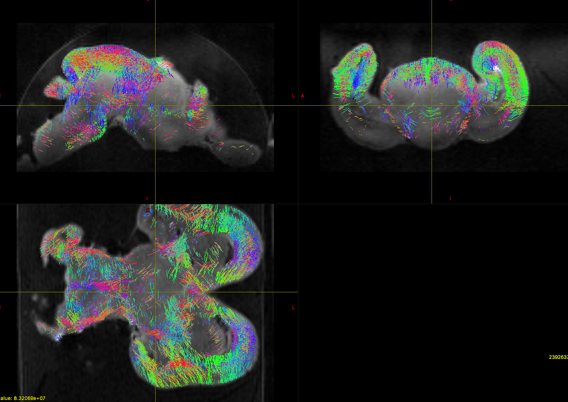
Secondly, attached is a picture of a sample track. What type of things would I look for, I understand e.g. red means right-left etc. But what type of things can a whole brain tractography tell me in terms of FA values. I understand this is a technical page, but I just need some guidance on the importance of tractography and some examples of how to analyse a whole brain tractography would be great.
So this is indeed not as trivial as it sounds… Basically, you want the single-fibre mask (as produced by the -voxels option of dwi2response) to correspond to deep white matter, in regions that you would expect to contain a single well-defined fibre orientation (i.e. not crossing fibres). This does require some anatomical knowledge about white matter anatomy.
Well, first thing is that you have a very strong bias field in your data, which translates directly into a bias field in the FODs (since they’re proportional to the signal), and hence in the tracking (since it uses a threshold on the FOD to terminate tracks). You really need to sort that out. There’s a script on MRtrix3 called dwibiascorrect that should help in this regard.
The other thing is it looks like the x & y gradients are swapped in your DW gradient encoding. I don’t know where you obtained that information, or what format it’s in, but this will need to be fixed too, by swapping these components around in the relevant files (rows in the bvecs, columns in the MRtrix3 encoding format).
Actually, you’ll find a lot of the discussion on this forum is also quite general. But I agree that more guidance as to how to perform basic tractography might be beneficial (this has come up a couple of times recently). However, it seems like you’ve managed just fine, and you’re already beyond what the basic tutorial covers.
So I’m not sure how easy it would be to provide what you’re asking. On the one hand, the issues you’re facing are specific to your data - this is very different from the standard in vivo case, where things should typically work more or less work out of the box. It’s difficult to predict all the issues that people might come across, and cater for all of them. In many ways, this is the purpose of this forum…
On the other hand, it seems you’re also asking for much more general guidance about diffusion MRI. This is something that you’d find in a review article (this one is particularly good ) - but you are of course welcome to ask for advice if you have a specific question.
We try to make this the case as much as possible. However particularly for images coming from animal scanners, this isn’t always the case: either due to the positioning of the sample within the scanner, or the output data provided by the scanner not conforming to a standard. It’s possible to manually permute the axes using mrconvert, but I think solving your bias field and gradient table woes are more pertinent right now.
But what type of things can a whole brain tractography tell me in terms of FA values.
I’m not sure that this question makes any sense: generating a whole-brain tractography reconstruction, and analysing FA values, are two entirely different things (unless you’re performing a very specific type of connectome construction, which I suspect is not the case). So I agree with @jdtournier that reading up on diffusion MRI articles or books would help in terms of formulating and articulating precisely what type of experiment you wish to perform.
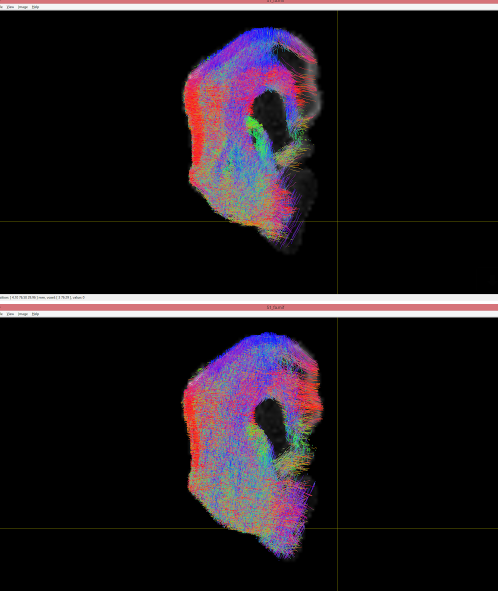
Hi, thanks a lot for your help. I have a few questions still. This is another tractography image I have gotten from another brain. One is mine (top one), the other (bottom) is from a classmate. Can you tell me if the bias field issues and the gradient swapping issues are present in this one as well? So I know the problem was Really with my last image, or something in the way I am processing it.
Also is there an automatic way to swap the x/y vectors in the gradient file rather than manually.
It’s really hard to tell from your images - I don’t even know what animal that is, and which way is up… But in terms of the orientations, they both look the same. The main difference here seems to be the use of a lower threshold for the lower one, allowing more streamlines in areas that would otherwise look sparse.
Also, any reason you’re using the old version of MRView…?
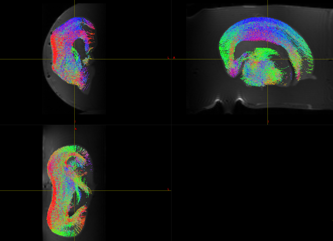
Right, the axial (bottom panel) looks OK: nice radial orientation in the cortex. But in the other two panels, you can see that the orientations go funny where they run at 45°: they should probably run orthogonal to that direction at that point. So this suggests the Z components of the bvecs need to be inverted.
I’m not sure we’re talking about the same thing here, so just to clarify: when you say ‘each picture’, you’re not just talking about each panel, right? Because the problem is there for the whole dataset, it just manifests much more clearly in the panels where the Z direction is in plane (i.e. the top two panels). An error in the Z is very hard to spot in the axial (bottom) panel since the directions that run in-plane are not overly influenced by the Z component - but things are going wrong there as well.
Again, that depends what you mean by ‘every time’. If you mean for all your datasets acquired with the same settings as what you’re showing, then yes, you’d need to correct them all. If you’re talking about each panel, then that doesn’t make much sense, the grad file applies globally - you can’t get it right for one panel and not for the others.
Yes: talk to whoever acquires or converts the scans for you, and get them to fix up their conversion tools…
Sorry I meant for dataset not panel, like a couple of posts above I showed another brain, and there were issues with x and y directions then. Here theres problem with Z.
So my question is,
when you mean theres problem with conversion tool, is there a problem with the dwi image or the grad encoding terminal file i was given.
Also how do you spot it, like I am very new to this program, are there any clues like when i look at a picture I can go…bam the x direction is not right etc. You did it for me before (z direction runs orthogonal, but I didnt quite visualise clearly what you meant).
How do i modify the gradient file (e.g invert the z components).
Lastly if I ignore your advice (as in if i find it too hard to implement) can I still get some proper analysis done on my pictures without doing anything to the image processing steps.
That’s actually really hard to say, you were using the old viewer with no indication of the projection you were using. All I could say is that the results were essentially the same in terms of orientation. For all I know, the problem might have been exactly the same.
Just the grad encoding file.
Use the force.
Kidding aside, it does take a bit of experience. But it’s basically geometry, you have to imagine what directions the fibres might be running in if you were to invert the X or the Y or Z component, etc. and see if that would be a better fit to what you expect to see given the anatomy…
Probably easiest in Matlab, or you could write a python script, or you could use awk if you’re a command-line die-hard like I am:
Not sure about ‘proper’ - but your ADC, FA, RD & AD values should be unaffected. But in general, it’s really important to get this right, it will come back to bite you eventually…