I am analyzing a simulated DWI dataset that was provided as part of the ISMRM 2015 Tractography Challenge (http://www.tractometer.org/ismrm_2015_challenge/). I am using the “artifact-free” dataset for this (b-value - 1000 s/mm^2; 33 directions), but have been facing a few issues with the tractography :
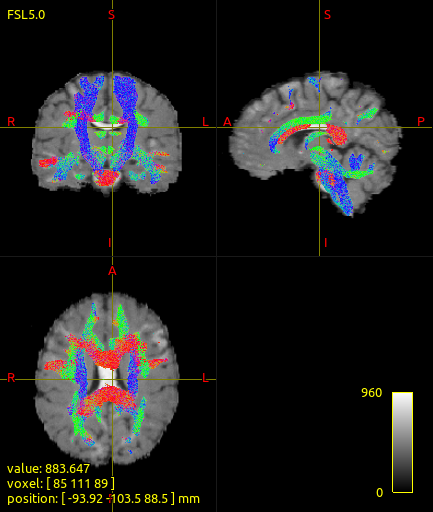
I cannot seem to track the callosal fibers very well. In fact, there seems to be a fair chunk of the corpus callosum that seems to go untracked.
The corticospinal tract also seems hard to track.
I have attached images illustrating my problem, and have also explained some details below (post-script).
I have not faced these issues when tracking fibers either with our own human subject dMRI data, or with data from other public databases (e.g. HCP). I wonder if this is a specific problem with this artificially constructed dataset. If anyone has insights about this problem based on their experience with analyzing this dataset (or otherwise), I’d greatly appreciate that.
Thank you.
Regards,
Varsha
ps: Details of tracking:
I have a 5tt image (5TT.mif) and brain mask (dwi_mask.mif) that I generated using the 5ttgen and dwi2mask commands respectively. With these I’ve checked the FODs as well as 5 tissue segmentation mask - these look okay. The FOD lobes seem correctly oriented in the corpus callosum, yet I cannot seem to trace fibers in that region. The specific commands I am using are the following:
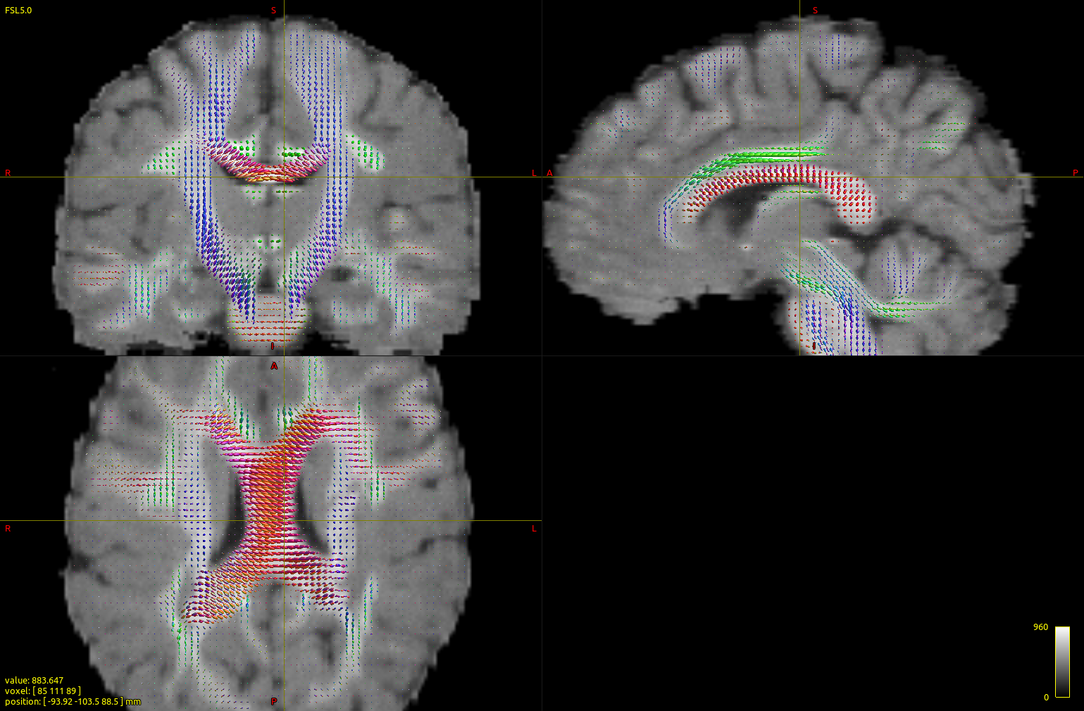
If you look at your FODs, their direction is not right. You can clearly see that on the corpus callosum on the coronal ODF projection. At the very least, it looks like the X direction is inverted in your DW encoding file. Looking at the axial ODF projection, I’d also be tempted to think there was a bit of a rotation within that plane too. Where did the directions come from? Did you do anything to the data before import? If using bvecs/bvals, be very careful to always use the bvecs/bvals with the exact image they correspond to. Any change to the orientation or the strides of the data basically invalidate the bvecs/bvals – one of the reasons we’re so keen for people to switch to .mif early in their processing pipeline…
Yes, I’ve used this dataset before myself. Simply flip the x-coordinate of the bvecs file before importing it using mrconvert. If you take care of that once at the start, and mrconvert it to .mif at the same time, you’re good.
There’s no other in plane rotation; apart from the x-flip issue, the dataset is quite clean and simple, without any rotations in the header. This is simply visually misleading in the image: the FOD angle in the midbody of the CC is not as strong as it seems (the FOD lobe width makes it seem a bit more drastic than it really is in this dataset). There is an angle though, but that is itself explained mostly by the fact that the mid-line of the brain isn’t neatly aligned to the grid here (which is again quite well hidden in the image, unless you look more closely). Once you do the x-flip and zoom out a bit, you’ll see it makes full sense.
Just for future reference for this particular dataset (i.e. the artifact-free one); a tip if you’d like to run dwi2response dhollander: add the -fa 0.1 option. The artificial nature of this “perfect” (noise free, etc…) dataset allows for that, and in this way, you get the best results.
Thank you @jdtournier for your response. I see where the problem is. I am using the bvals and bvecs files as supplied with the DWI data and have made no modifications to it. The first step in my pipeline is exactly as you mention - to convert to .mif using the mrconvert command, by providing the bvals/bvecs to be encoded into the DW image.
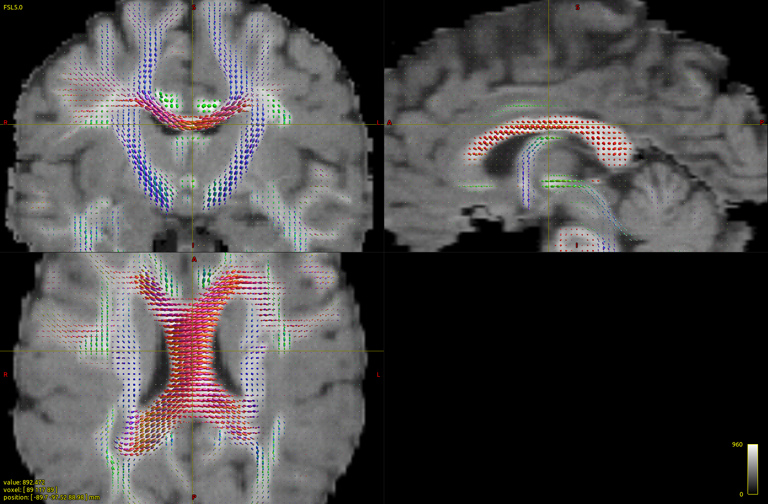
Based on your comment, I did played around with the bvecs file a little by flipping the signs on the x coordinates and regenerated the FODs. The orientation directions seem to be correct now.
I guess there truly was a mismatch between the bvecs and DWI data. However, I’m not sure if just flipping the left and right based on a visual inspection is the right way to go about it. Is there a way to ensure that the bvecs/bvals are consistent with the DW image and automatically do a flip if necessary? Also, the rotation in the axial plane seems to have been somewhat fixed with this correction to the bvecs. Would you have any suggestions regarding this as well?
Thanks @ThijsDhollander. This is exactly what I did and the results seem okay now (response above).
Just for future reference for this particular dataset (i.e. the artifact-free one); a tip if you’d like to run dwi2response dhollander : add the -fa 0.1 option. The artificial nature of this “perfect” (noise free, etc…) dataset allows for that, and in this way, you get the best results.
I am using the bvals and bvecs files as supplied with the DWI data and have made no modifications to it.
Most likely those responsible for generating / providing the data fell for this gotcha just as we did. Indeed if you were to load these same data using an older version of MRtrix3, i.e. before we fixed this bug, the two errors would have cancelled each other out, and the FODs would be oriented appropriately.
However, I’m not sure if just flipping the left and right based on a visual inspection is the right way to go about it. Is there a way to ensure that the bvecs/bvals are consistent with the DW image and automatically do a flip if necessary?
dwigradcheck is intended as a data-driven check for such issues. It can never be “ensured” that the gradient table is correct, but it will make its best guess as to what any error may be.