I followed the HCP tutorial with my own data, and got 2 questions that I can’t find answer.
I used the command ‘trkgen’ with option ‘-select’ the command was
tckgen WM_FODs.mif 10k_number.tck -act 5TT.mif -backtrack -crop_at_gmwmi -seed_dynamic WM_FODs.mif -select 100000 -maxlength 250 -cutoff 0.06
and it selected 100000 stream lines,
I loaded the output ‘.csv’ file into my matlab and checked the total numbers of edges.
It was a 84x84 matrix.
I expected the total of elements (which are number of stream lines) would be 100000, because I selected that number, but the answer was 65634.
I think about 35000 streamlines are missing.
Do you know the reason why this happened?
Another question is about the ‘nodes_fixSGM.mif’ image
I created the image by the tutorial and visualized it.
I looks like that subcortical graymatter (BG and thalami) is in wierd location…
I used the T1w image resistered to MNI space with 1mmx1mmx1mm resolution, and everything else was same as HCP data(it uses 0.7mm resolution).
I wonder the resolution is the cause of this mis-registration.
The number of streamlines you generate with tckgen is the final number of streamlines stored in your tractography, but this differs from the number of elements in your connectome for different reasons:
1.- If you select the option -zero_diagonal in your tck2connectome, you are removing all the self connections, so the final number of elements will be less than the selected number of streamlines. In a ideal world, if you include the diagonal in your connectome, the number of streamlines should be the same as the elements in your connectome, but…
2.- not all the tracts reach a GM ROI termination, even tough you are using ACT. You can find a nice abstract about this here
The second question, I don’t know, but I’m guessing that the images you are using for the process are not well aligned.
I looks like that subcortical graymatter (BG and thalami) is in weird location…
Yes, something has definitely gone wrong there. I encountered this issue constantly when I first wrote that script, and had hoped that the mechanisms in place to ensure alignment would be adequate, but you may or may not have found an exception.
The first thing to check would be to ensure that the parcellation and T1 images provided to labelsgmfix are in fact aligned with one another. Make sure that you use the Overlay tool in mrview to check this, rather than flicking between the two images. If you have applied some rigid-body transformation to only one of the two images, then there’s a chance that they may have the same voxel size & dimensions, but their header transformations differ; the Overlay tool will highlight this. If there is a misalignment between these two images, then the actual issue is in the handling of the image data upstream to the labelsgmfix script.
If these two images do genuinely overlap in scanner space, but labelsgmfix is still producing images such as that provided, then I’ll need to get a copy of your data and attempt to reproduce the fault.
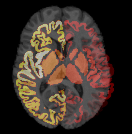
Here’s my mrview overlayed image and I think you diagnosed the problem.
The background T1 image is an image registered to MNI space and the overlayed parcellation is right out of Freesurfer.
I made this mistake because I thought the ‘T1w_acpc_dc_restore_brian.nii.gz’ image in MRTrix tutorial is MNI-resistered image.
Now I think that I was wrong. Is ‘T1w_acpc_dc_restore_brian.nii.gz’ just brain-extracted native T1 image?
To confirm,
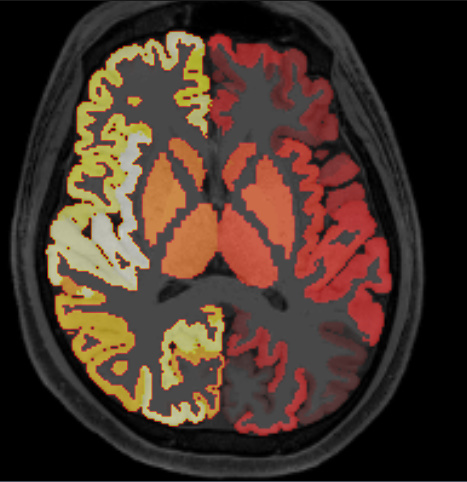
I tried with native T1 image and parcellation outcome.
and it results in
I think it’s in right place.
Sorry to bother but I’ll leave this reply just in case someone makes same mistake.
No, it isn’t. It is anterior-posterior comissure aligned ( therefore acpc in the filename ) image, corrected for gradient nonlinearity distortion (not indicated in the filename), B0 inhomogeneity readout distortion ( dc ) and bias field ( restore). However, this is a space FreeSurfer reconstruction in HCP pipelines takes place. Therefore, your FreeSurfer parcellation aligns with T1w_acpc_dc_restore_brain.nii.gz.
Now I understand what ‘T1w_acpc_dc_restore_brain.nii.gz.’ is.
Do you know is ’ ‘T1w_acpc_dc_restore_brain.nii.gz.’ a ordinary output of Freesurfer 'recon-all’
or some special manipulation is needed to get that image?
T1w_acpc_dc_restore_brain.nii.gz is output of PreFreeSurfer HCP pipeline, so it is actually an input to FreeSurfer’s recon-all (which is main part of FreeSurfer HCP pipeline). Not sure what you mean by output of recon-all; recon-all produces many files (surfaces, parcellations,…), so the answer depends on the goal you want to achieve.