Hi,
I came across an problem when using sh2peak to get the orientation vector. Here is the command:
sh2peaks wmfod.mif -num 1 peaks_first.nii.gz
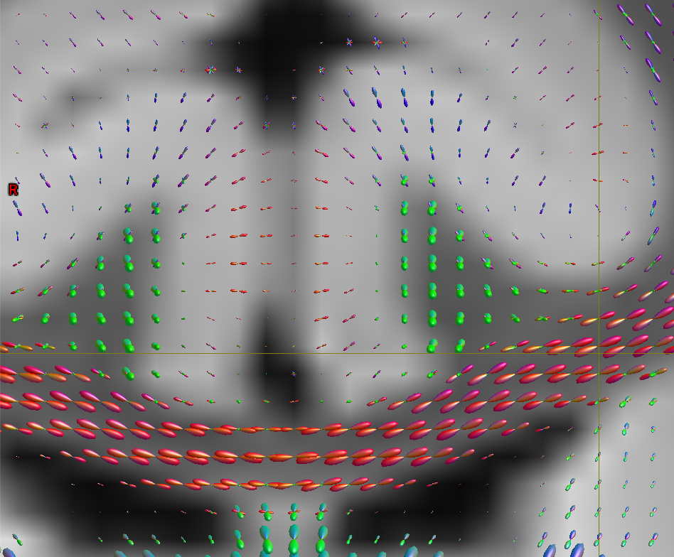
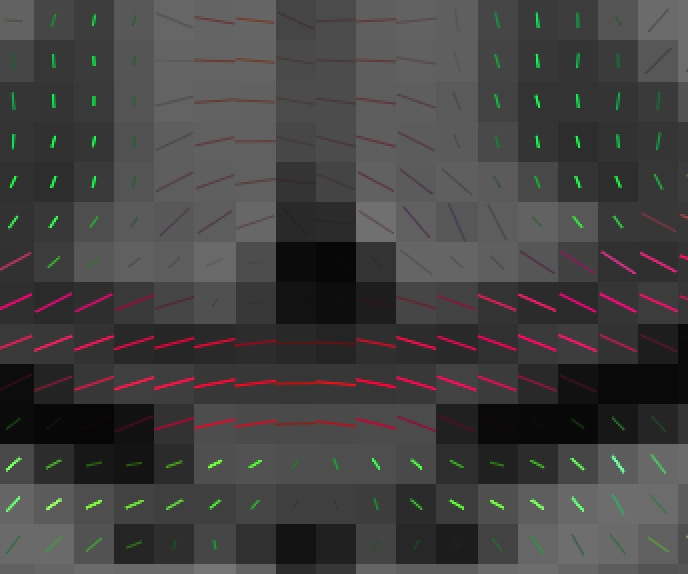
Then, I checked the nii image with fsleyes, finding the orientation is inconsistent with the odf visualized in mrview. The red lines in the center are in CC, while the vectors looked wrong.
If you visualise the extracted peak orientations using the Fixel Plot tool in mrview, you should find orientations that are consistent with the ODFs.
What’s most likely happening here is the consequence of different conventions for how orientation information is encoded. In MRtrix3, all orientation information is defined with respect to the three spatial axes of the acquisition scanner hardware, referred to as “real space” or “scanner space”. In the FSL software, orientation information is defined with respect to the directions of the image axes; referred to as “image space” or “voxel space” (which can be fractionally different depending on the context, but I think we can skip past that detail here). While this is now reasonably well documented for diffusion gradient directions, the same logic applies to derivative DWI data such as fibre orientations (though not sure about whether the FSL flipping X direction for radiological images also applies to fibre orientations in FSL).
If the image data happen to be perfectly axially aligned, there’s a good chance that negating the value of the x-component will do the trick. If your image data are oblique then the requisite transformation is more complex; I don’t actually think we have anything in MRtrix3 for the conversion, there’s probably at least one person out there that’s written some form of converter.
Hi, rsmith
Thanks for your comphrehensive answer. Yes, it’s right when visualized in mrview. While I’m still confused that the “transform” is identity except for a placement of the origin as you can see with mrinfo. So the orientation represented in both space is expected to be … the same, isn’t is? Or the mrtrix did some extra transform when converting a DWI data to .mif fomat?
Yes, it’s all a bit confusing. The transform relates voxel indices to their location in 3D space, but orientations are stored according to different conventions. In MRtrix, they’re stored relative to the real space coordinate system. In FSL, they’re stored relative to the image axes. So that means components (1,0,0) in MRtrix points along the scanner x-axis, while in FSL it points along whatever direction the image’s x-axis is pointing along. And on top of that, there’s an additional quirk when handling FSL directions (see here for details, it’s the same for bvecs/bvals). There’s no right and wrong here, just different conventions…
I stumped upon this problem and thought my rotation solution might help someone one day.
Basically from Mrtrix SH coefs, I used sh2amp to estimate the FOD amplitude at N directions (Nx3 matrix). These directions are in scanner space (world space).
If you want to display the FOD glyph in Matlab or the peak in FSL, you need to “rotate” this set of directions to “voxel space” by using the transformation from nifti header.
In Matlab it’ll be
header = niftiinfo(imageIn);
transform = header.Transform.T’;
% % % change Mrtrix convention to voxel convention
R_voxel_to_world = transform;
R_voxel_to_world = R_voxel_to_world(1:3, 1:3);
% Ensure it’s a pure rotation matrix (remove scaling/skew)
[U, ~, V] = svd(R_voxel_to_world);
R_voxel_to_world = U * V’; % Corrected rotation matrix
% Compute inverse transformation (Scanner → Voxel)
R_world_to_voxel = inv(R_voxel_to_world);
% Convert directions from MRtrix (scanner space) to MATLAB (voxel space)
direction_matlab = (R_world_to_voxel * direction_mrtrix’)'; % assuming direction_mrtrix is N x 3