I am creating structural connectomes based on the Human Connectome Project pipeline. I saw some discussions on registering diffusion images to structural (T1) images on the forum, and I was wondering if this is a necessary step to take at the beginning of the pipeline.
On the website, it says if no diffusion distortion correction applied, then non-linear registration is an option to consider. For a diffusion image, I am using the ones that have been denoised and eddy-corrected, and generating tractography based on anatomically constrained tractography framework.
I ran 40 people so far, and 3 of them are missing about 4 nodes. I was wondering why that is the case. Is there a possibility that some subjects are missing nodes because I am not registering dwi images to T1 in my pipeline?
I am creating structural connectomes based on the Human Connectome Project pipeline.
Presumably you’re not talking about using the HCP data itself, as in that case you’d simply use the minimally pre-processed data for which inter-modality registration has already taken place. If you’re trying to perform pre-processing of your own acquired data using the HCP pre-processing scripts, it was my belief that the post-eddy stage is responsible for registration between DWI and T1…
For any non-preprocessed data, registration between T1 and DWI really should be done. It’s not uncommon for participants to hear the MR scanner stop between protocols, and shimmy around to reduce pressure on uncomfortable areas of the head.
If nodes within the parcellation are “missing from the connectome”, meaning that not a single streamline terminates in / adjacent to that node, then that’s indicative of a gross alignment problem. Loading your DWI data in mrview, and then opening your T1 image using the “Overlay” tool in mrview should give you an idea of the magnitude of misalignment. Another approach is to feed your parcellation image through the labelcolour command, open that image in mrview, and also open the tractogram using the “Tractography” tool; that will show you the data that tck2connectome is operating on in its raw glory.
Thank you so much for the super helpful reply, and I apologize for the delayed response. I wanted to check a couple of things before posting an update because these posts seem to be really useful for MRtrix users.
Yes, that is correct. I am not using the HCP data. I checked the alignment as you have described. It turns out my parcellation and DWI were sightly misaligned. I decided to register my DWI (or b0 image specifically) to T1 using flirt from FSL using boundary-based registration. Then, I used transformconvert and mrtranform to get the transformation matrix in MRtrix format and register my DWI to T1, respectively. After implementing this in the pipeline, those subjects were only missing 1 node or none, instead of 4. (i.e after tck2connectome, the error says so.)
In some other post, I have seen that registering T1 to DWI was also useful. I then registered T1 to DWI using the inverse transformation matrix from above.
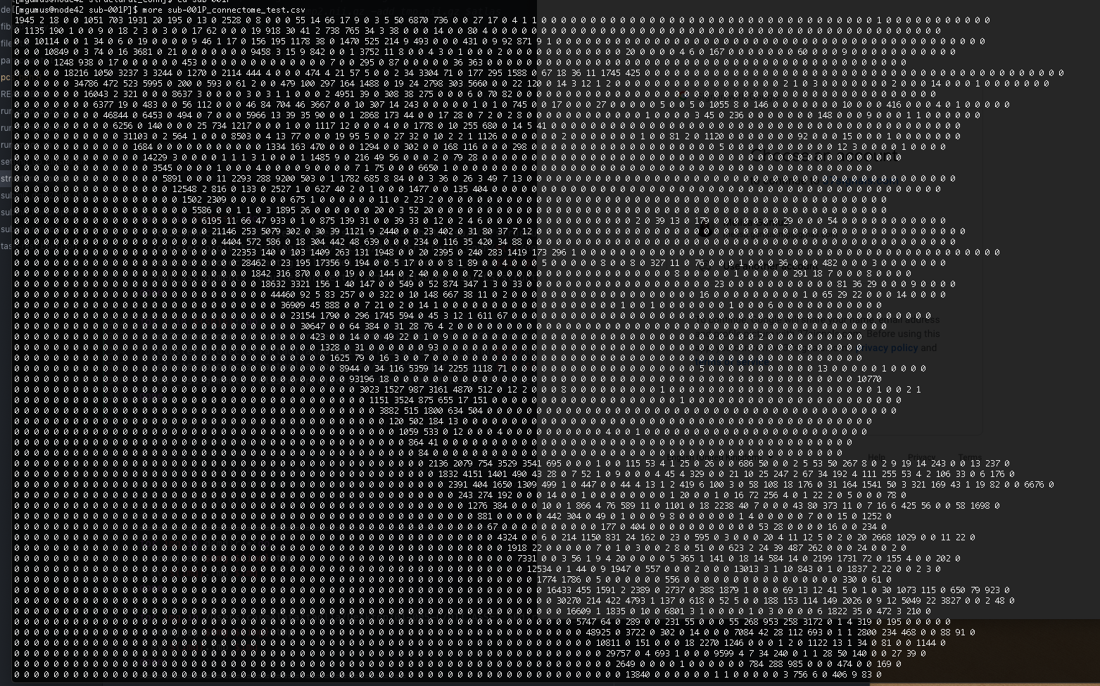
Now, none of my subjects is missing any nodes, and everything seems to be fine; registration, 5TT images… However, I have another weird issue. In the connectivity matrix, half of the entries are 0s. (I am not referring to it being asymmetric.) It looks like this:
I am using the default atlas, Desikan-Killiany. I create 20M streamlines with tckgen using ACT framework, seeding from gray-white matter interface, and then sift that to 2M.
I have no idea where this problem might be coming from. It might be hard to comment without seeing the entire pipeline and the data, but do you have any ideas on why I am getting this weird looking connectivity matrix? Maybe someone else had a similar problem before?
There is any problem here, this is the default behaviour of tck2connectome.
If you add the option -symmetric, it will do a symmetric output matrix. Also if you are interested the option -zero_diagonal, will make the diagonal 0 (remove self connections). I hope this helps.
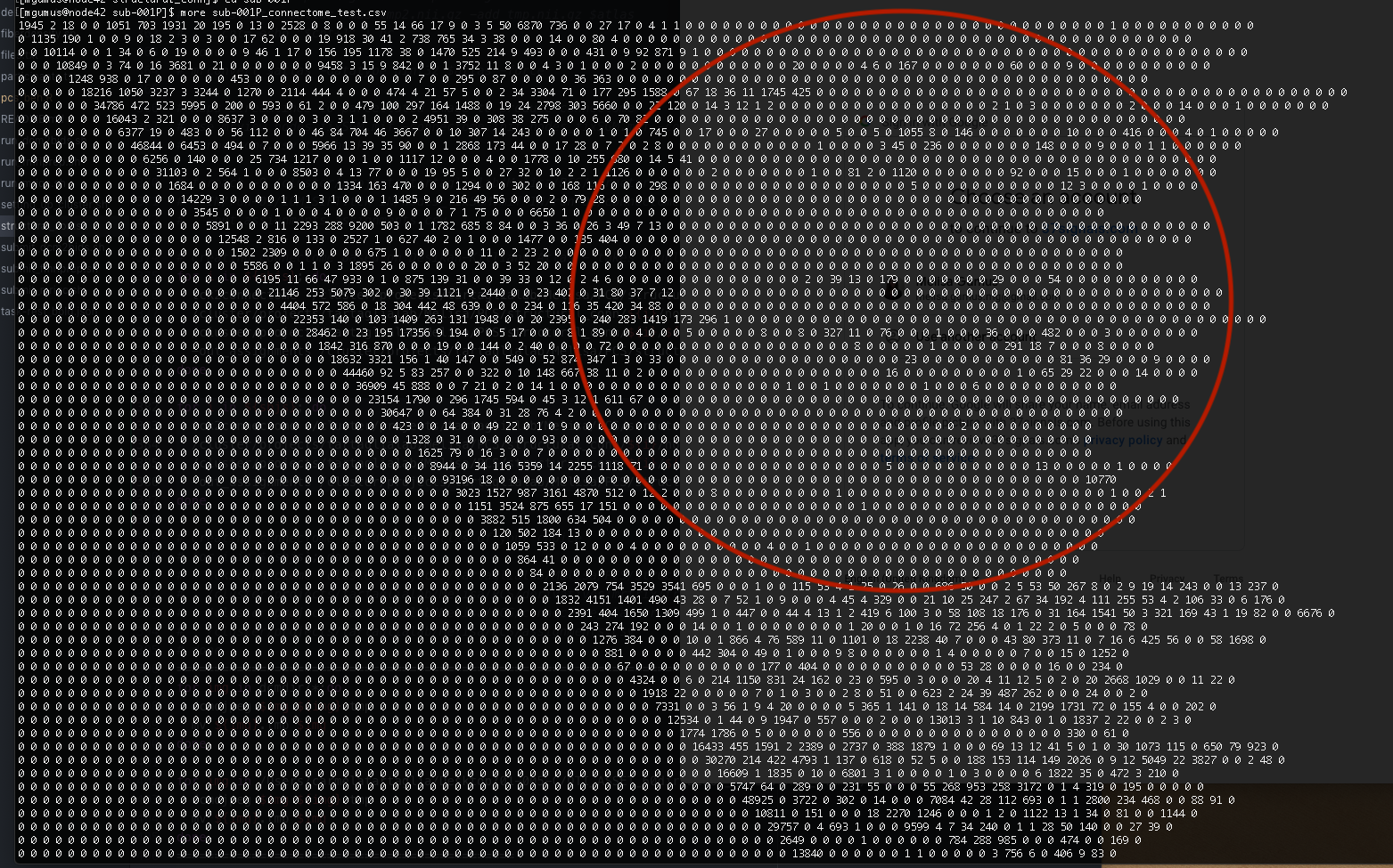
I have been thinking about the connectivity matrix, and realized that those zeros in the circle are actually referring to the interhemispheric connections. I guess there are not many of those of connections between right and left hemisphere, so I started to think that maybe the connectivity matrix I posted is correct…
In that sense the matrices look fine for me. I belive that this will vary a lot depending of your experimental design, if you use ACT or not, the mask and the seeding strategy, etc. but as I said they look fine.