Hello community!
I’m working on an analysis of an individual tract in the brain using track orientation density imaging (TODI). I have tractograms (or.tck) for 20 subjects. In brief, I’m having trouble with
- transforming FODs into an MNI template (am I missing a key point about effectively transforming FODs?)
AND - normalising FODs (am I going about this correctly?)
(I can achieve 1. and 2. individually, but not combined)
The aim is to have an average, normalised orientation distribution map of the tract in an MNI template space (I’m using MNI152, originally 1mm voxels, downsampled to 2.5mm to match subject diffusion).
By normalised I mean an orientation distribution function in each voxel that integrates to 1.
I’m using the track orientation density image (TOD) obtained by
tckmap -tod 8 OR_tractogram.tck tod.mif

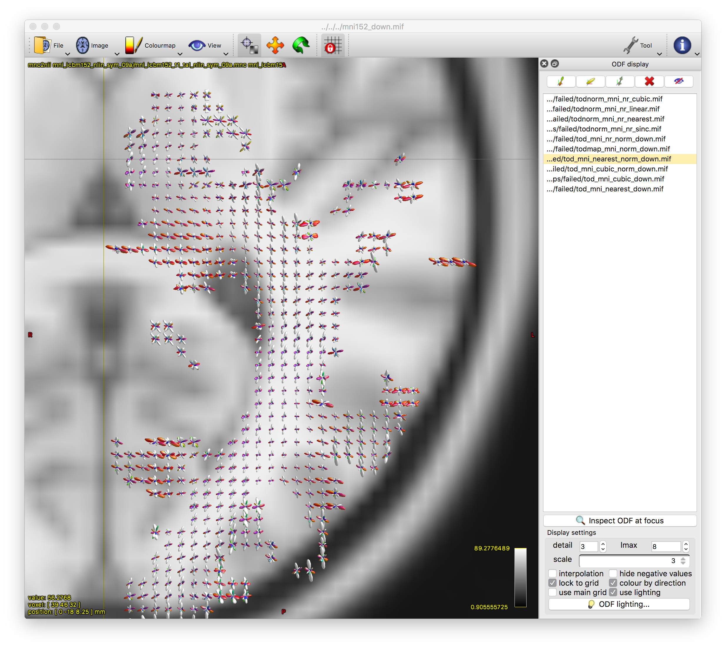
The output tod.mif (above, right) contains the (scalar) track density information which I want to normalise out, to obtain a pdf.
My understanding is that this effectively equates to dividing the full TOD by the first TOD spherical harmonic coefficient and sqrt(4pi):
mrconvert -axis 3 0 tod.mif tod0.mif
mrcalc tod.mif tod0.mif 4 pi -mult -sqrt -mult -div todnorm.mif
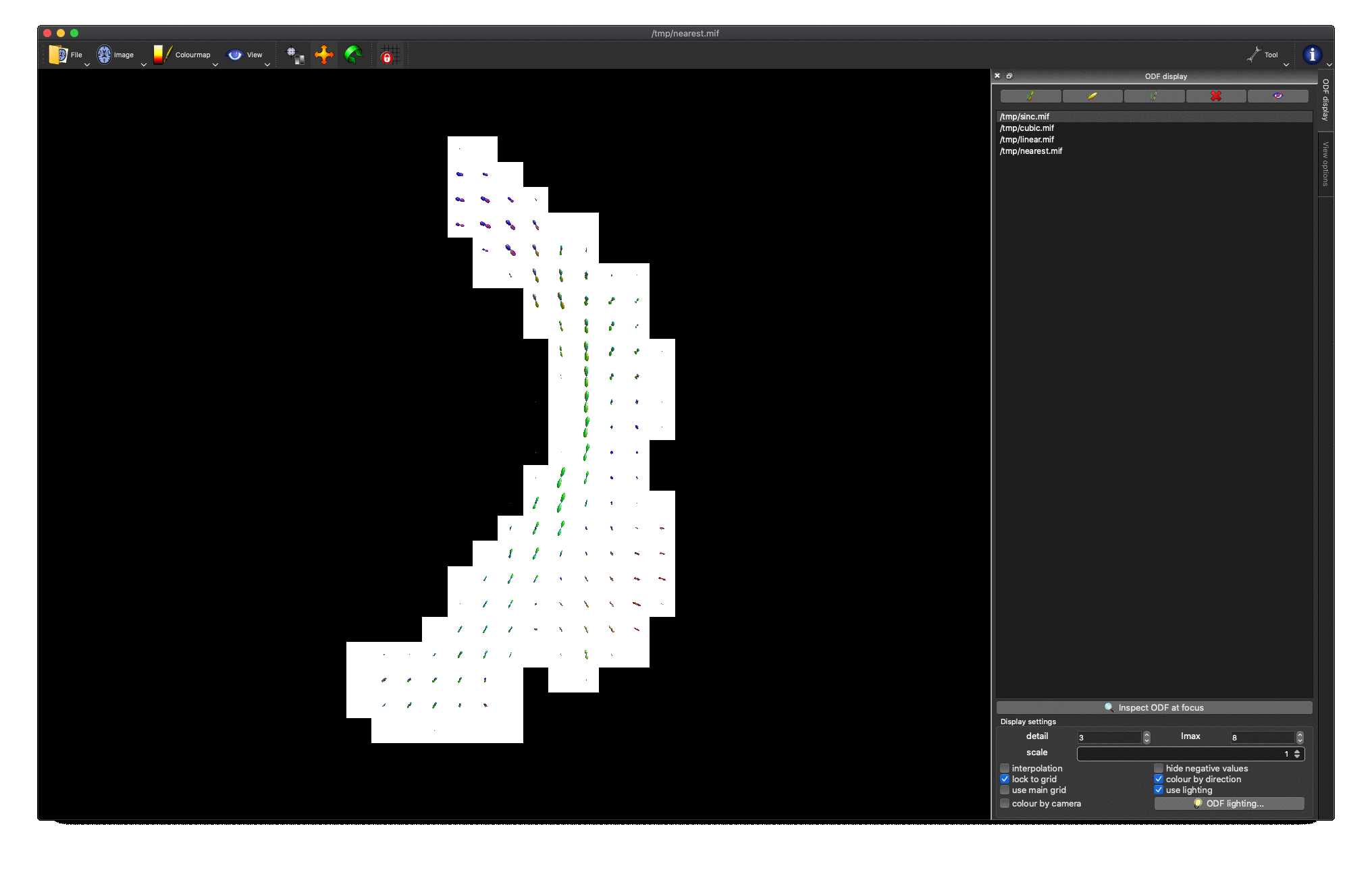
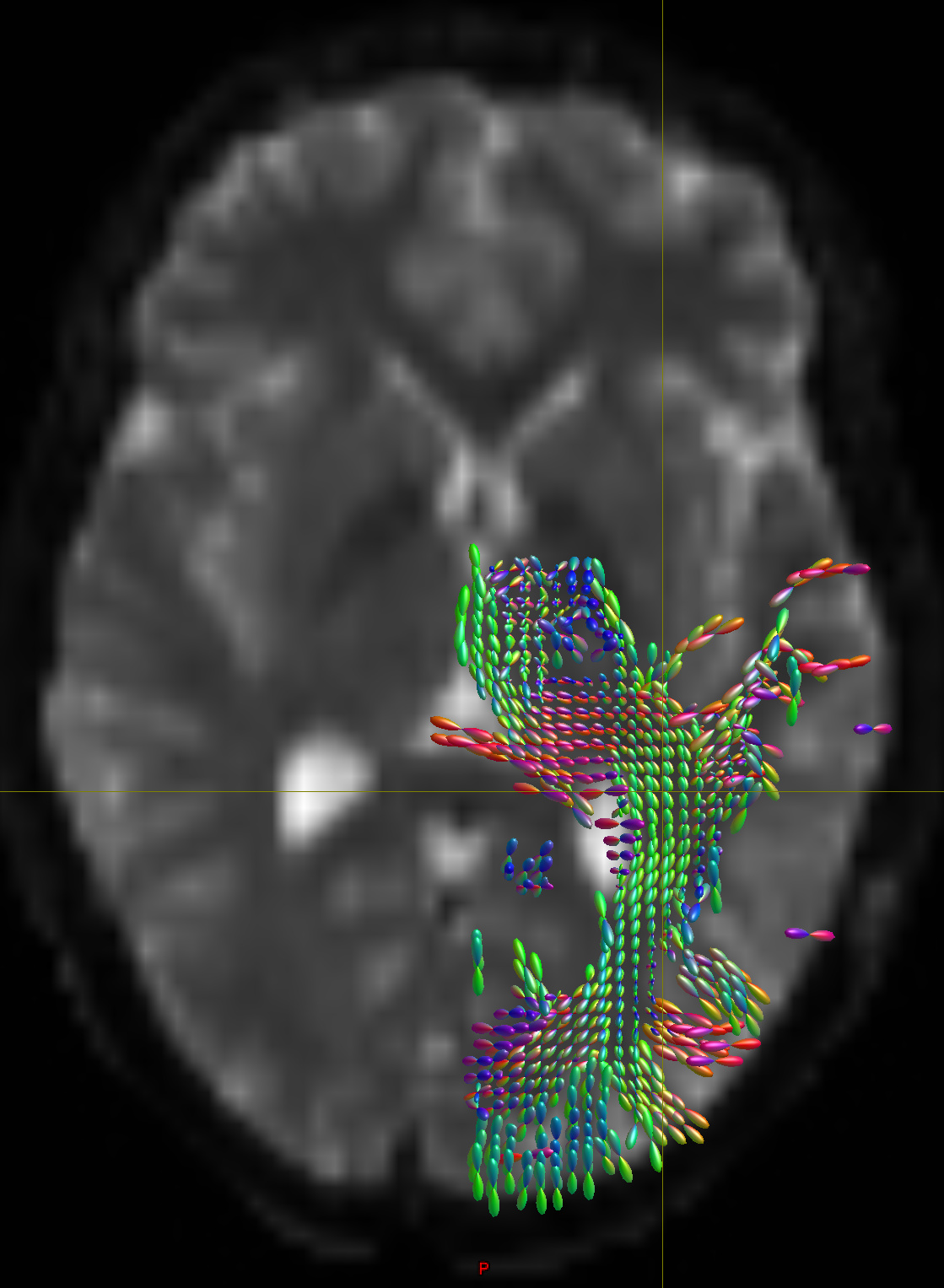
This works really nicely in subject diffusion space:
I’m having less success when adding registration into the mix.
Each subject has a T1 image which has already been aligned with subject diffusion space.
Using fsl’s FLIRT, I’ve registered each subject T1 to the MNI template (affine, 12 dof),
converted the transformation to mr format, and transformed the subject TOD images.
mrtransform -linear t_t1_2_mni_mr.txt -template mni152_down.mif tod.mif tod_mni.mif
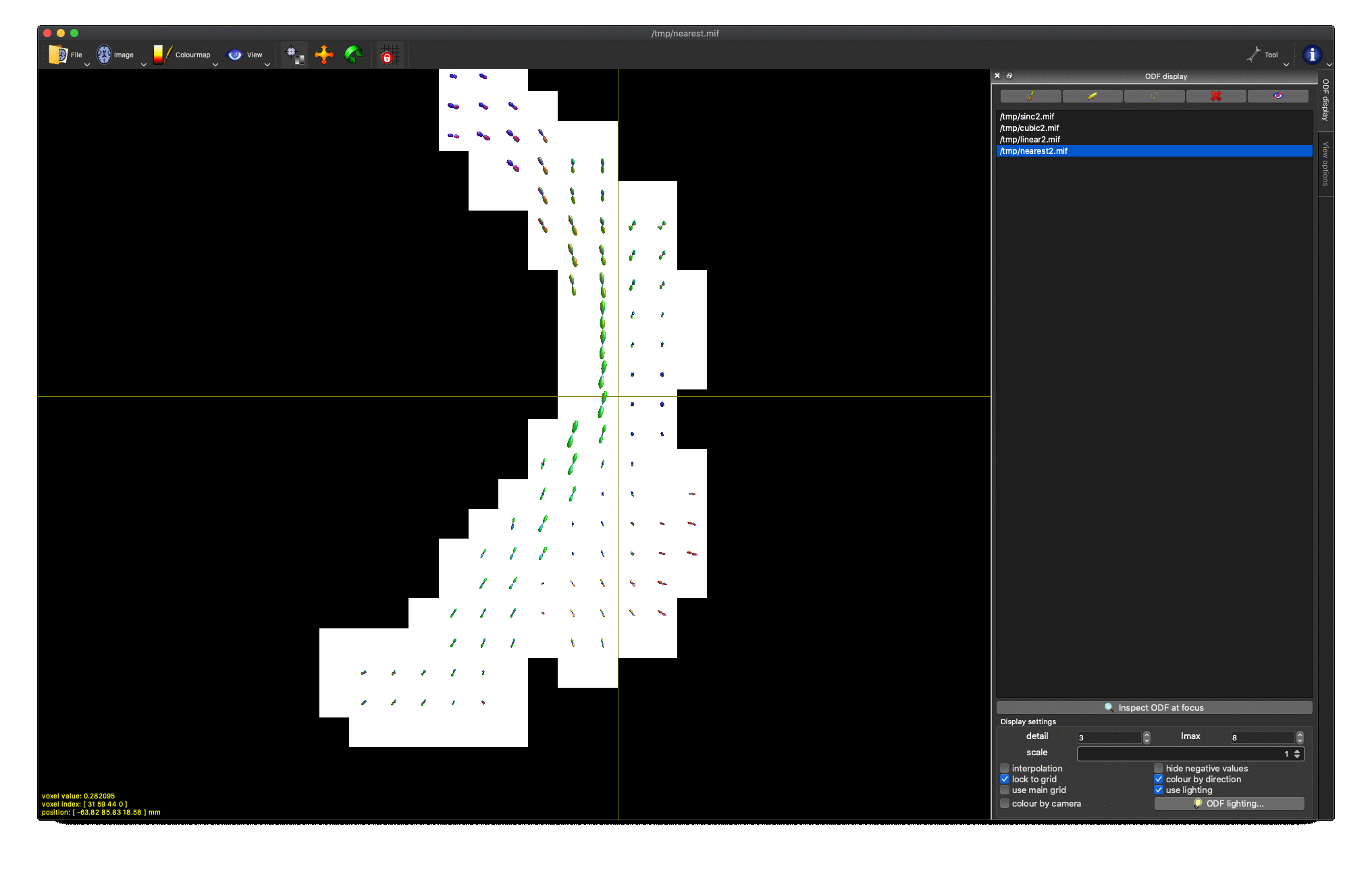
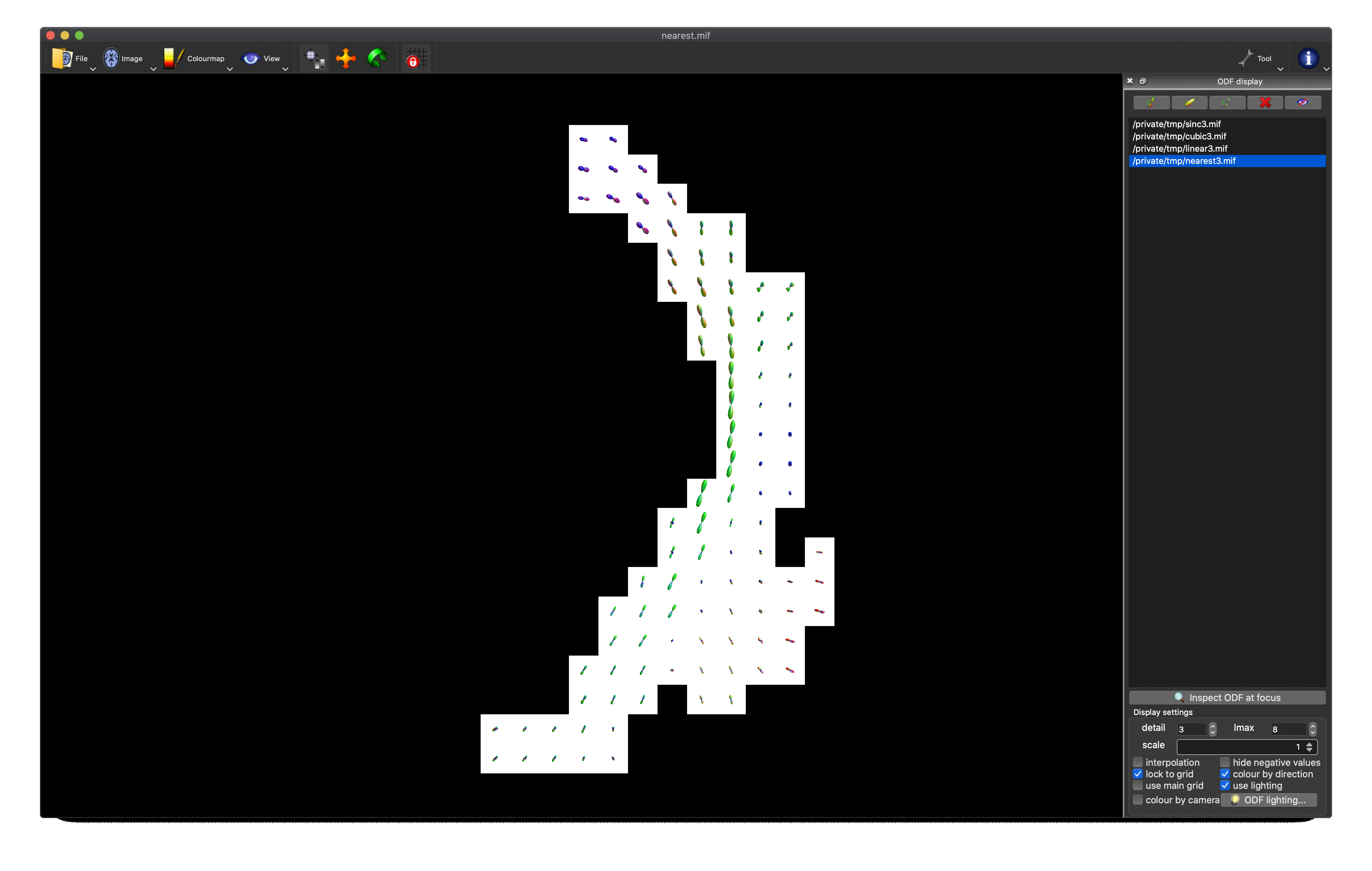
I can’t seem to achieve a well behaved, normalised TOD map in MNI space.
I’ve tried (put simply):
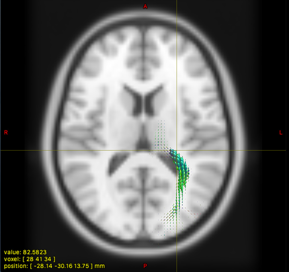
- normalising in subject space, then transforming
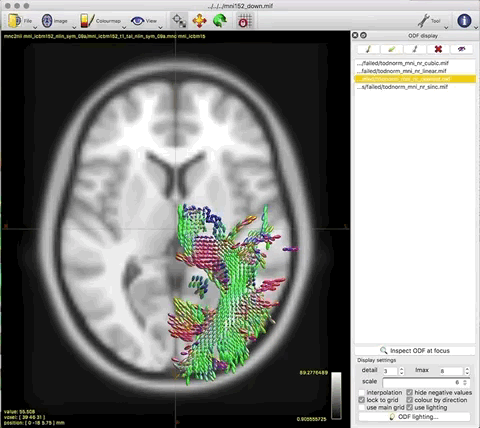
- transforming, then normalising in template space
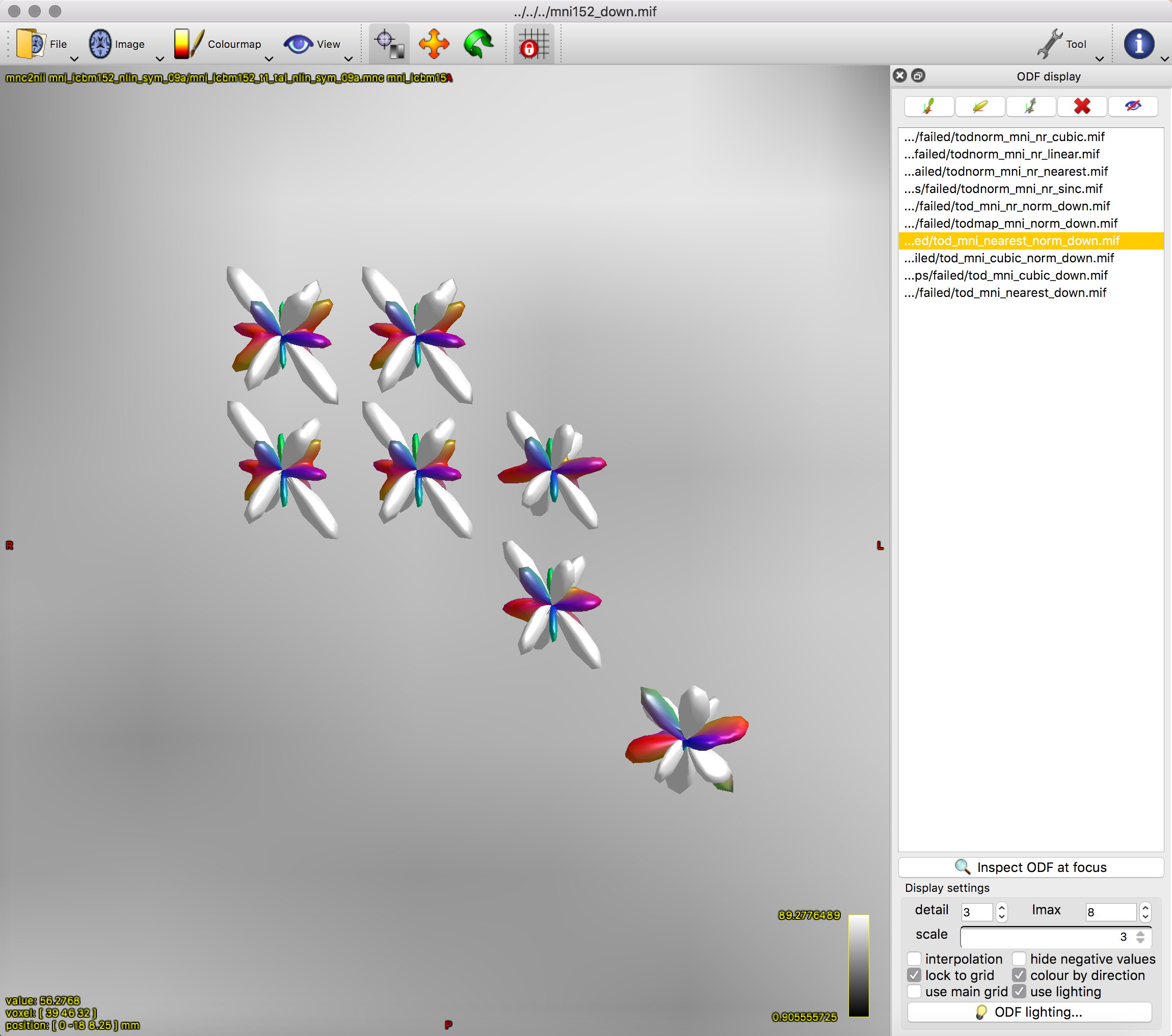
Option 1. results in a large reduction in the apparent extent of the tract,
as if lots of the tract ODFs at the edge have been suppressed to zero:

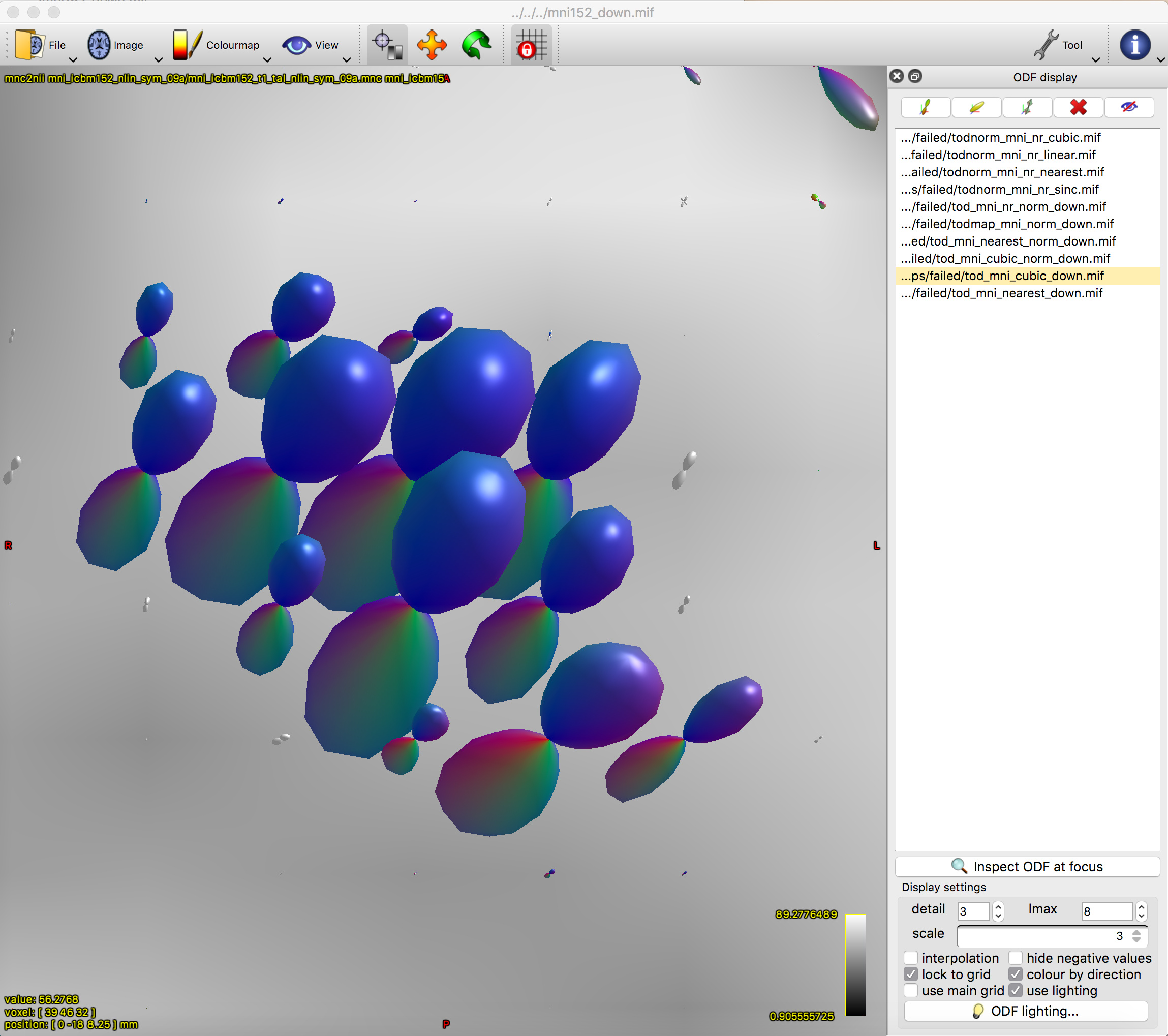
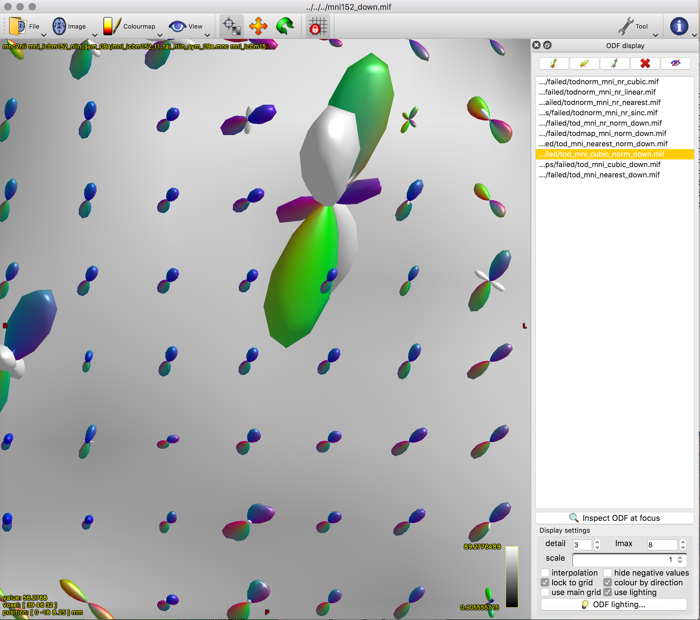
Option 2. results in a (seemingly random, although typically located in low track density regions) selection of ODFs blowing up and gaining negative lobes:

Things that look fine:
- normalised TOD in subject space (above, 3rd image)
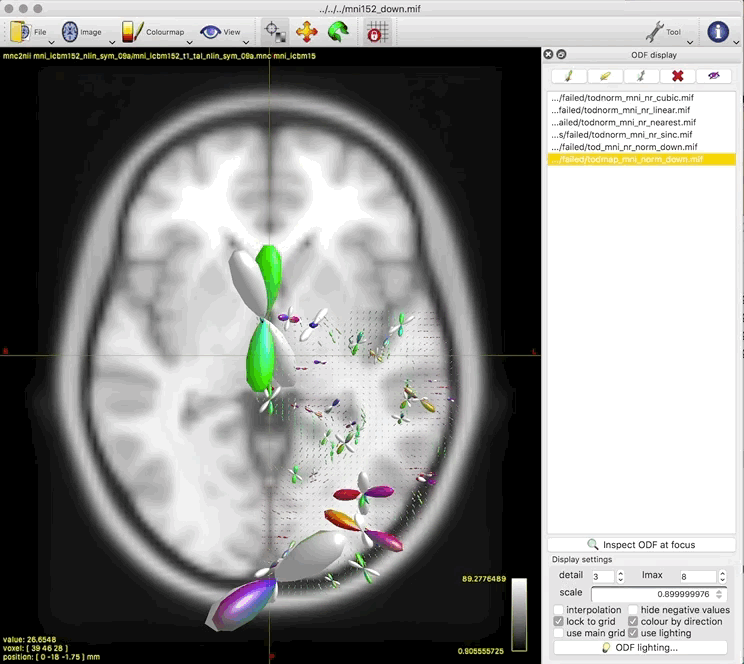
- unnormalised TOD transformed to MNI:
I have only a limited understanding of SH ODFs, and particularly the reorientation process using apodised PSFs, but I had a suspicion that small numbers and rounding errors might be the culprit. However, first scaling the TOD map by 200 before transforming and normalising made no noticeable difference, so now I’m really at sea. I’ve also attempted creating the TOD map at higher angular resolution (up to lmax 14) to no avail. Any tips / experiences appreciated!
MRtrix version: 3.0_rc3
OS: Mac OS X 10.13.6
Cheers,
Fiona
Side question: What does the “interpolation” option in the mrview ODF display tool do? When I uncheck it, a whole bunch of extra ODFs appear at the edges of the tract, and the rest are unchanged. All of the above images have this ODF interpolation turned off.
[Apologies for the long post, I tried to keep it to the point while including enough useful details]
 )
)


 But, to make sure I get it right (so do correct me if I don’t!), we’re essentially talking about 3 main operations here: