When I use “tckmap” to convert the 2015 ISMRM challenge ground truth tck file to TOD or dixel image, an error of “no step size information in track file header” occurred. The tckinfo shows there is only track count information contained. I viewed the tck and a template image in mrview, and they were aligned well.
So, how can I add the aditional information in the header? Or is there other way to solve this problem? Thanks!
It’s not surprising that these data won’t contain step size information, since they will have been converted from whatever format they were produced in into .tck using some external conversion software.
My response in a similar recent thread here likely provides the solution: Manually provide the -upsample option to tckgen, so that it no longer depends on this track header information.
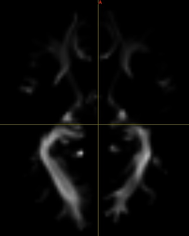
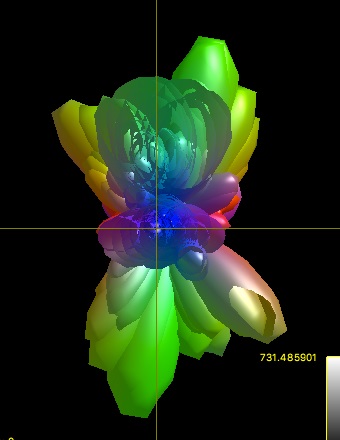
The SH based TOD image is quite normal seen from the first coefficient. However, when I load it as SH image in ODF view, it looks strange.
The intensity range of the TOD SH coefficients is much larger than the FOD SH coefficients. I am wondering are there any guidelines for TOD visualization and implementing the TOD tractography?
Thank you very much!
Yes, that looks like it’s simply a scaling problem. The ODF tool does a pretty direct interpretation of SH amplitude as length in mm in 3D space. This works fine for fibre ODFs: if the DWI magnitude and response function amplitude are approximately matched, then the ODF l=0 term in purely white matter voxels will be about 0.282 (1/sqrt(4pi)), this will be the mean ODF amplitude across all orientations in such voxels, and this happens to provide a pretty good spatial scaling of ODF size with respect to image voxel size. However with a TOD, the ODF magnitude scales directly with the number of streamlines in the voxel; hence the mean ODF amplitude may be thousands of times larger in magnitude if there are thousands of streamlines within each voxel.
While in your second image it looks like a bunch of ODFs are transposed on top of one another, I believe this is because you have zoomed out a very long way, so the voxel centres are very close to one another in the 2D projection onto your screen. What you need to do instead is scale the size of the ODFs with respect to the underlying image space, rather than zooming out. This can be done using the “scale” value in the mrview ODF tool. Try setting it to e.g. 0.001 upon loading the TOD and see what happens.
I think the TOD paper had some suggestions on scaling the TOD amplitudes in order to re-use them with a tractography algorithm? Otherwise @ThijsDhollander can comment further on this.