Vector orientation confusion between MRTrix and FSL in rat data

Hi all,

I have been tackling this problem for a few weeks now, to no avail. I’ve read up on similar orientation posts here and on the older MRTrix 2 FAQ and still have yet to solve the issue. So, I’m posting here hoping some of the experts can help.

I have rat DWI from a Bruker machine, which is converted to ANALYZE using the pconv tool, then converted to NIFTi via an in-house script which multiplies the voxel size by 10, applies orientation labels, generates sform/qform, and reorient the data via fslswapdim. With the reorientation, of course we’d need to double and triple check our bvecs and bvals, and have settled on a working bvec which gives the correct orientations using known anatomical landmarks. All of this, so far, is done through FSL, and is our current working model.

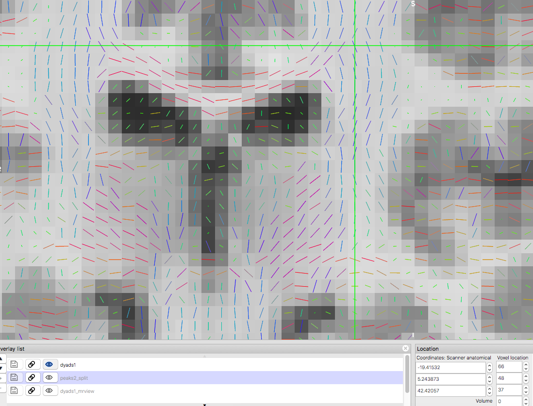
Vectors generated using FSL’s DTIFIT. Note the blue nerve bundle running anterior-posteriorly.

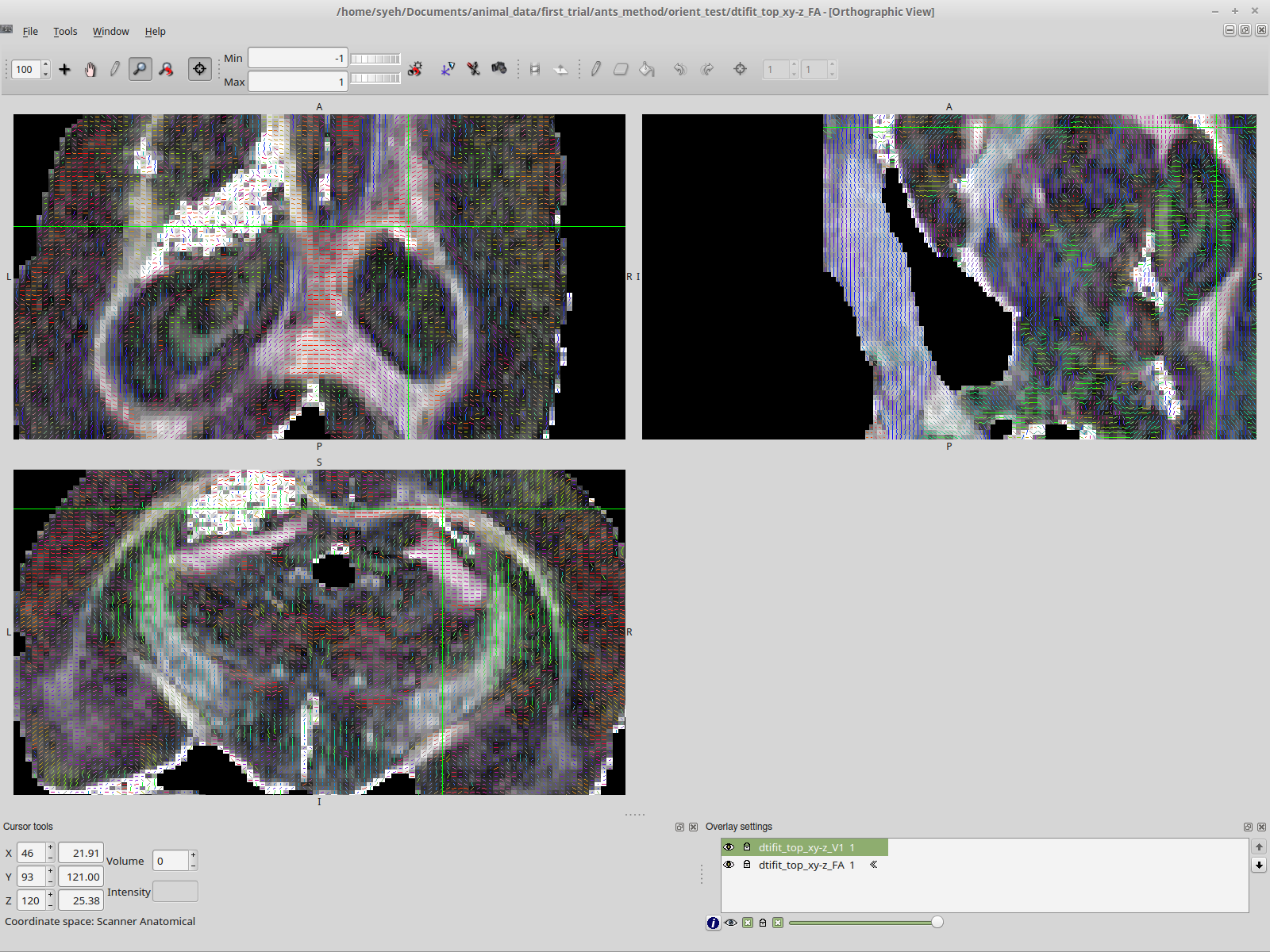
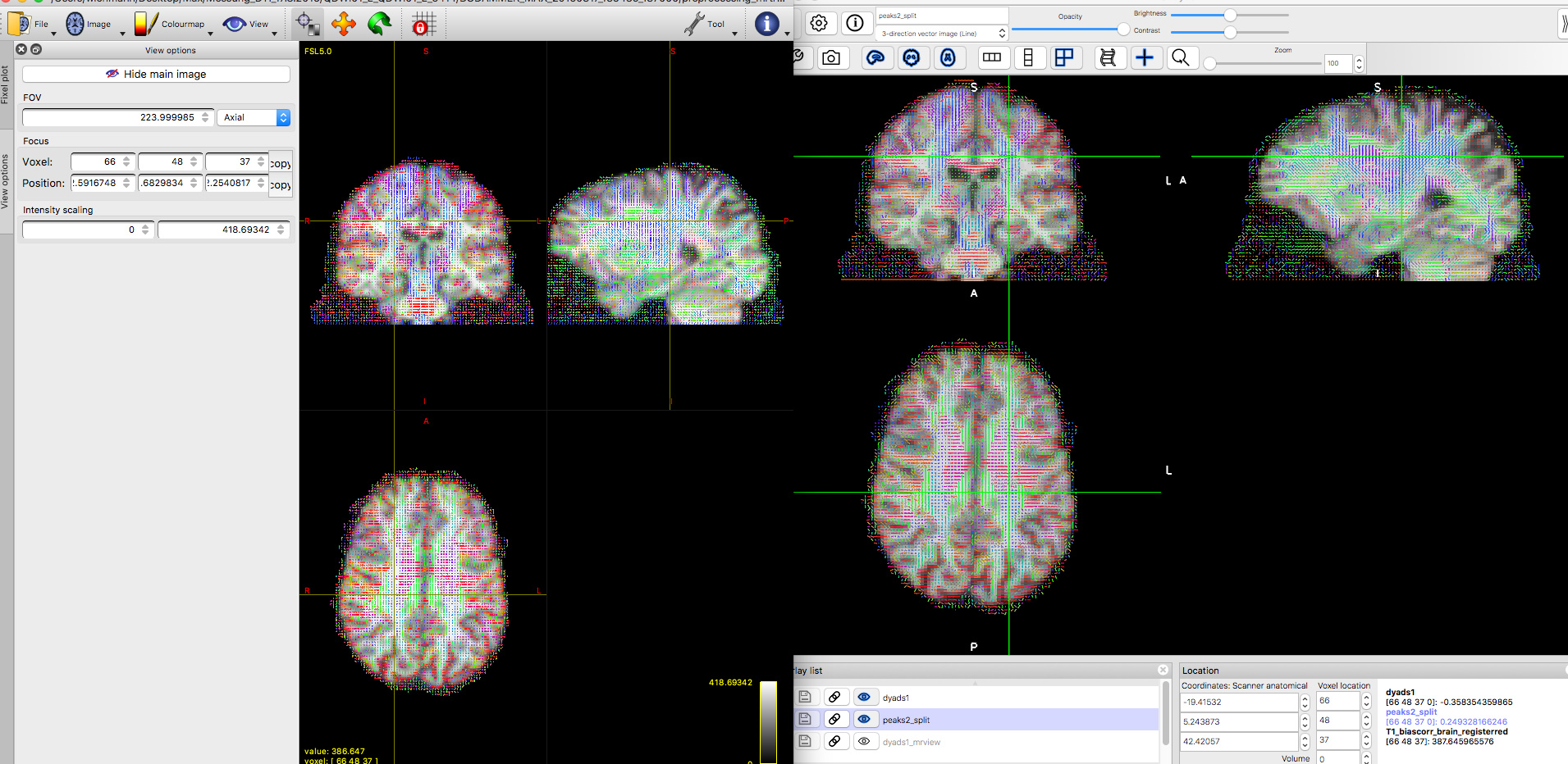
Now, we are attempting to replicate the result in MRTrix, and almost everything is the same, except for the vector colors.

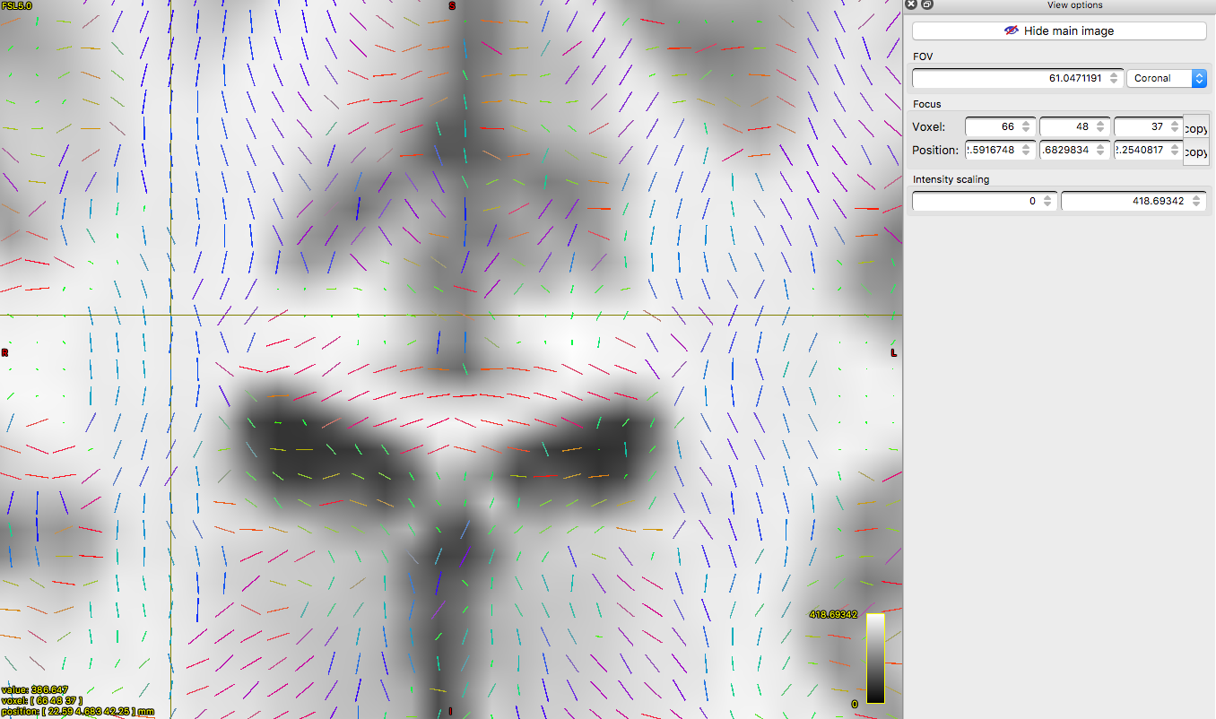
Vectors generated using MRTrix. Note that the previously blue nerve bundle now is green. Vector directions are the same as previous image.

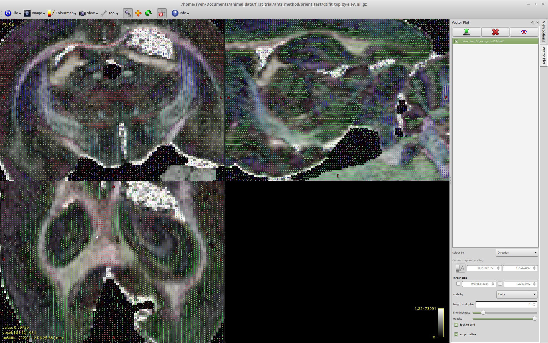
This is where the rabbit hole starts.

I have since then played with the strides, mrtransform, manually edited the gradient files using trial and error, and nothing works. It’s especially confusing when you have multiple factors that could all be a contributing factor.

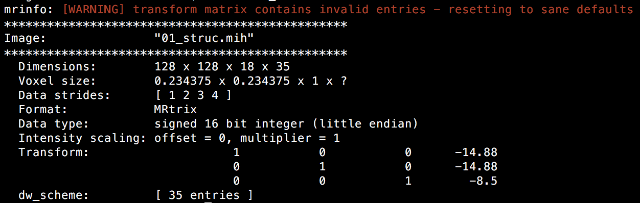
The closest I’ve come to getting anywhere is if I convert the DWI to mif format using mrconvert and then convert back to nifti:

mrconvert -info -stride 1,2,3,4 -fslgrad ../../../bvecs_xy-z.txt ../../../bvals.txt ../dwi_top.nii.gz dwi_top_fslgradxy-z_s1234.mif
mrconvert -info -export_grad_fsl exp_bvecs2.txt exp_bvals2.txt dwi_top_fslgradxy-z_s1234.mif dwi_top_fslgradxy-z_s1234_conv.nii.gz

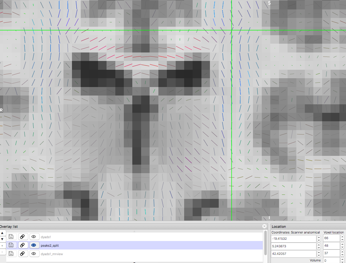
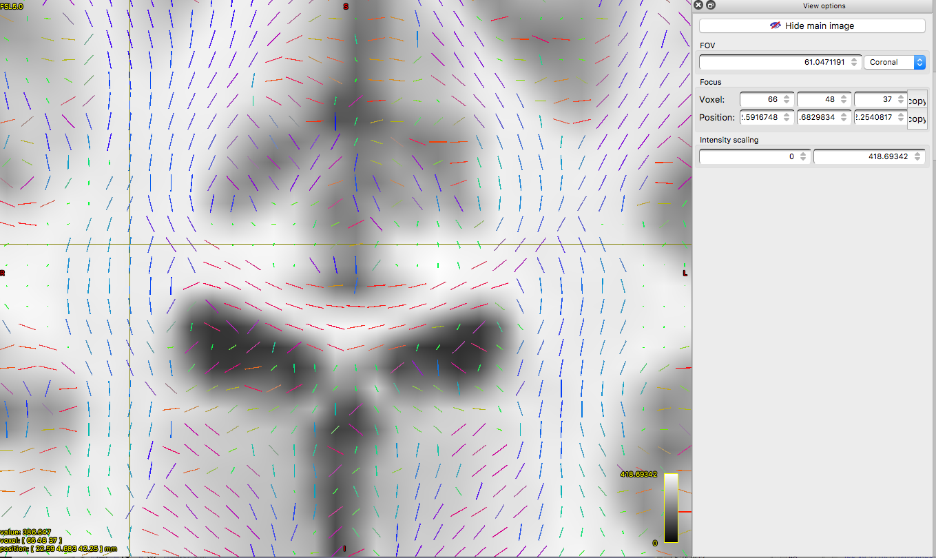
Then, I run FSL’s DTIFIT on the new nifti file, using the exported bvecs and bvals (which are quite different than the original). This is what I get:

Vectors generated using DTIFIT, with converted bvecs, bvals, and nifti.

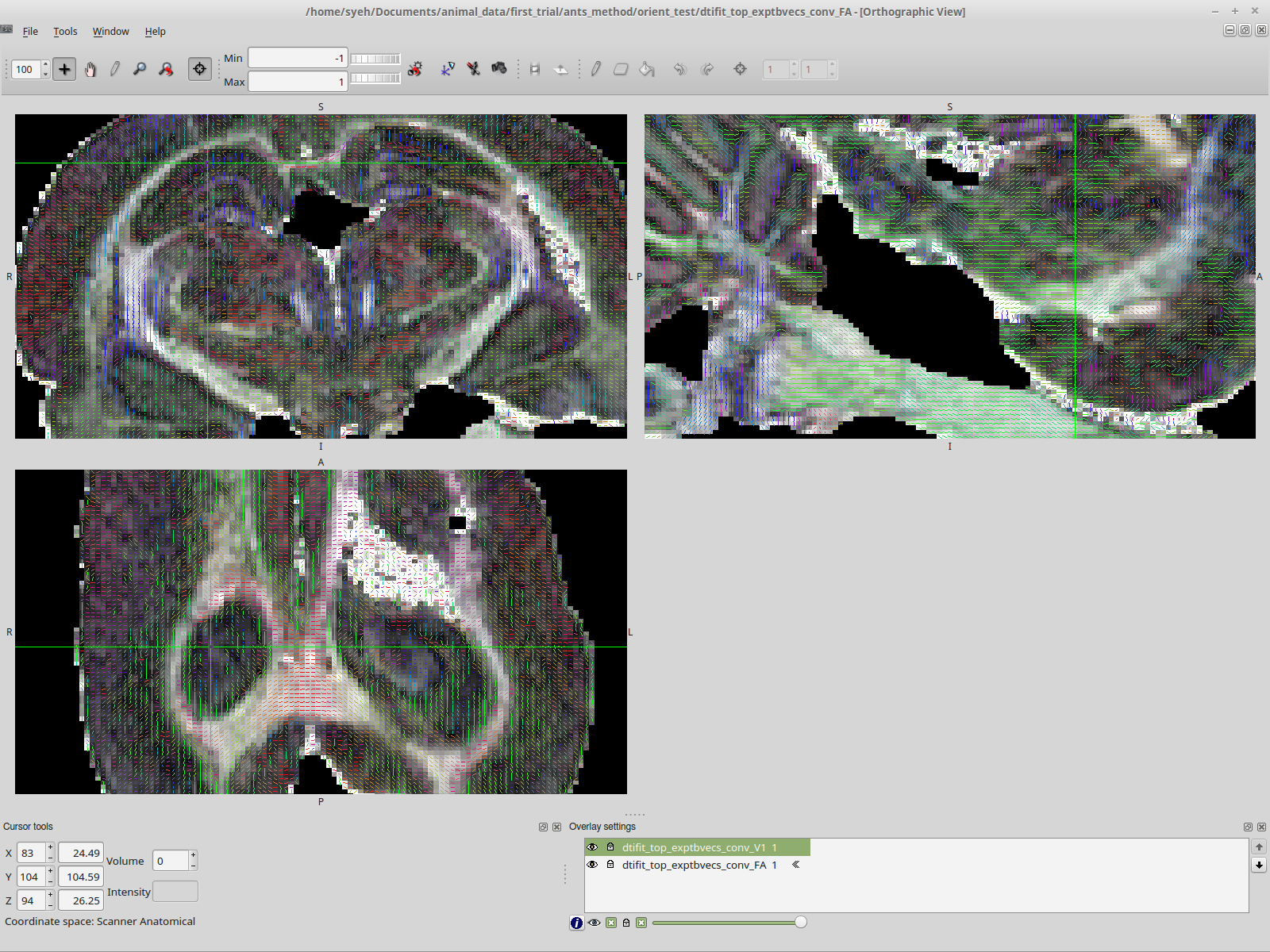
This is at least consistent with the MRTrix result, the second image. The vector directions are all the same as the MRTrix result, right down to the green instead of blue nerve bundle.

Where do I go from here? What I want is to display the nerve bundle as blue, which I thought would’ve been a trivial matter. However, it has been anything but trivial.

-Shawn

This is similar to a similar discussion going in this thread. In your case however, the MRtrix results look correct: the image is displayed in the correct orientation (assuming inferior-superior maps to ventral-rostral, and anterior-posterior to rostral-caudal), and the direction vectors are the right colour for that coordinate system. I assume the nerve bundle you are referring to the large structure (trigeminal nerve?) visible in the top-left panel? If that’s the case, then it should be green: it’s oriented rostral-caudal, and in all packages is displayed as anterior-posterior, which by convention is assigned to green. Displaying it as blue would imply it’s oriented as inferior-superior (ventral-dorsal), which is at odds with what the packages are actually displaying, as well as my (limited) knowledge of rodent anatomy…

However, it could also be argued that in a rodent system, rostral-caudal is generally aligned with the scanner z-axis, in which case it would be displayed in these packages as inferior-superior, and hence that structure would be coloured in blue. I’m not sure what the right answer is here, it depends on the conventions used in the rodent world, and how the scanner sets up the coordinate system (on human systems, the coordinate system is actually set at exam time relative to the anatomy via the DICOM patient-based coordinate system, so doesn’t need to be aligned with the scanner as such).

Note that (for your first FSL screenshot) the image is also interpreted correctly in FSL, in that the orientation labels are as expected and match those with MRView. The directions are not however coloured correctly with respect to the anatomy - they are the ‘right’ colours with respect to your display. In other words, if the top-left panel had been labelled as I-S for the vertical direction (i.e. the NIfTI standard coordinate system in the absence of rotation) instead of A-P, then the cingulum and trigeminal are shown in the expected green colour, rather than blue (which is the right colour for an I-S orientation) - this is confirmed in your second FSL screenshot, where the images are displayed with the expected standard orientation in FSLView (by using the -stride 1,2,3,4 option in mrconvert). I’m not familiar with how FSLView decides how to colour their tracks, but evidently they use the display coordinate system. In MRtrix3, we try to do everything in real/scanner/world coordinates if possible, and that means the images are displayed relative to that coordinate system, and therefore with the expected orientation (i.e. the top-left pane should always show a coronal section, with R-L on the horizontal axis and I-S on the vertical axis), and the colours are always determined in that frame also. This means the display is independent of the details of how the images were stored (i.e. basically what strides were used).

Two more tiny comments:

  • there is a script in the scripts/ folder called convert_bruker, which is provided on a best-effort basis to help import Bruker data. It converts to one of the MRtrix3-specific formats (.mih), from which you can convert to NIfTI or whatever you see fit. It should try to also import the directions (bvecs/bvals), and so might help avoid all this hassle. Note however that it is known not to get everything right, particularly for obliquely-acquired data, and sometimes the DW orientations aren’t in the right frame. But it might nonetheless help sort out some of these issues.

  • your conversion from NIfTI to NIfTI via the two mrconvert calls can be performed in a single step, no need to store to an intermediate .mif file:

      mrconvert -info -stride 1,2,3,4 -fslgrad ../../../bvecs_xy-z.txt ../../../bvals.txt ../dwi_top.nii.gz -export_grad_fsl exp_bvecs2.txt exp_bvals2.txt dwi_top_fslgradxy-z_s1234_conv.nii.gz

Thank you for the detailed explanation! It definitely cleared up a lot questions, which up until now we can only guess comes from the differing coordinate/color systems between the FSL and MRTrix packages. I’ll refer your answers to my colleague who is more experience with rodent work and discuss our options.

We’ll also look into the convert_bruker option and see how that goes. And thanks for the hint on mrconvert, I didn’t realize you can convert a NIfTI to NIfTI in one step!

Hello team, A follow up question to this thread …
We’re utilizing convert_bruker script to extract the gradients direction information from the method files. However, to correct for the difference in acquisition of the rodent vs human from the scanner, we require to change the dimensionality of the header file of nifti e.g. to have our images in the correct coordinate. Would you please let me know if we also need to apply the same dimension change to the gradient vectors?

Can you explain this a bit more? Maybe post the output of mrinfo on your data before and after your modifications, and also the command you use to ‘change the dimensionality’? I have to admit, I’m struggling to understand what you mean… :confused:

Apologies … Below, please find a header information screenshot of one of the datasets after convert_bruker script.

However, opening the corresponding mif image in mrview, displays the picture upside-down. It makes sense since the images are acquired upside down as we place the rodent in prone position but we’re setting the scanner to supine! I know it’s strange :slight_smile:

That’s why I need to move the direction back to the standard and wasn’t sure how to do it in mrtrix (if possible) and also if we need to apply the same changes in direction to the gradient vectors.

The command you’re looking for is mrtransform -linear, and yes, it will reorient the DW gradients if present in the header. From the docs on that command:

If a DW scheme is contained in the header (or specified separately), and the number of directions matches the number of volumes in the images, any transformation applied using the -linear option will be also be applied to the directions.

You’ll need to provide it with the transformation to apply, in the form of a file containing the 4×4 matrix. If the image is upside-down, I’m guessing something like this will do the trick:

-1  0  0  0
 0  1  0  0 
 0  0 -1  0
 0  0  0  1

This flips both x & z, which should correspond to a 180° rotation about the y axis.

Thanks a lot. I always admire the amount of support you and your colleagues provide to the community.

1 Like

Or even faster: mrtransform -flip :sunglasses:

1 Like

Hello together,
I would like to ask some similar question.
When I view my orientations (peaks) in Fsl they look incorrect. For example they go up instead of down. The same thing happens when I load Fsl orientations in mrview. So the Mrtrix (peaks) orientations are correct in mrview the Fsl (dyads) orientations are correct in fslview.
Following this topic I guess just the way how they are visualised is different. I guess the L/R orientation is reversed when I put in the same voxel allocation. I tried to reorientate via -stride command but nothing changed? I guess I can not use the stride command inside the 4th dimension on the vector components? So my questions are:

  1. What I have to change so that I can compare directions in Mrview or Fslview?
  2. Do just the Viewers itself load the data in a different way or are the calculated results of the orientation different? Because I would like to do some calculations with the peaks files in Fsl and with the dyads files in Mrtrix I need to know if I have to transform the vectors just for visualisation or also for all other use?

Here are some pictures which explain the problem:

Thank you for this great community support !
Max

1 Like